G120 -Getting Started

Written by Matthew Clark-Massera
Updated at May 22nd, 2024
Table of Contents
The G120 is a compact 2G or 4G Cat-M1/Nb-IoT GPS tracking device with a variety of inputs and outputs to cater for the most demanding applications.
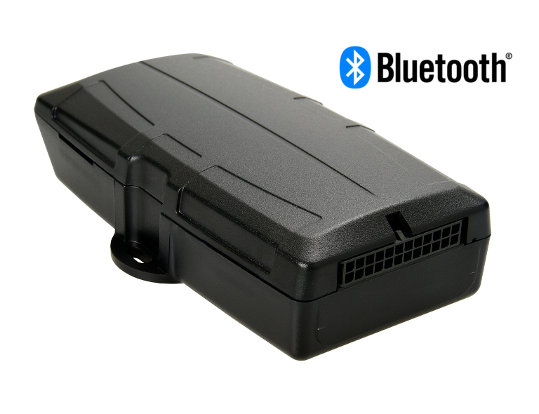
With the internal GPS and cellular antennas installation is a breeze. The internal backup battery provides alerts and tracking operations even when external power (8-45V) is removed.
The G120 is equipped with a Bluetooth v5 module, enabling it to act as a Bluetooth Gateway and is also Iridum compatible with the addition of an Iridium Edge module via the G120 wiring harness. This enables a nearly plug and play option for out of cellular coverage tracking.
digitalmatter.com
Datasheet & High Resolution Images
G120 Downloads
View the latest tech-specs and high resolution device images for the G120
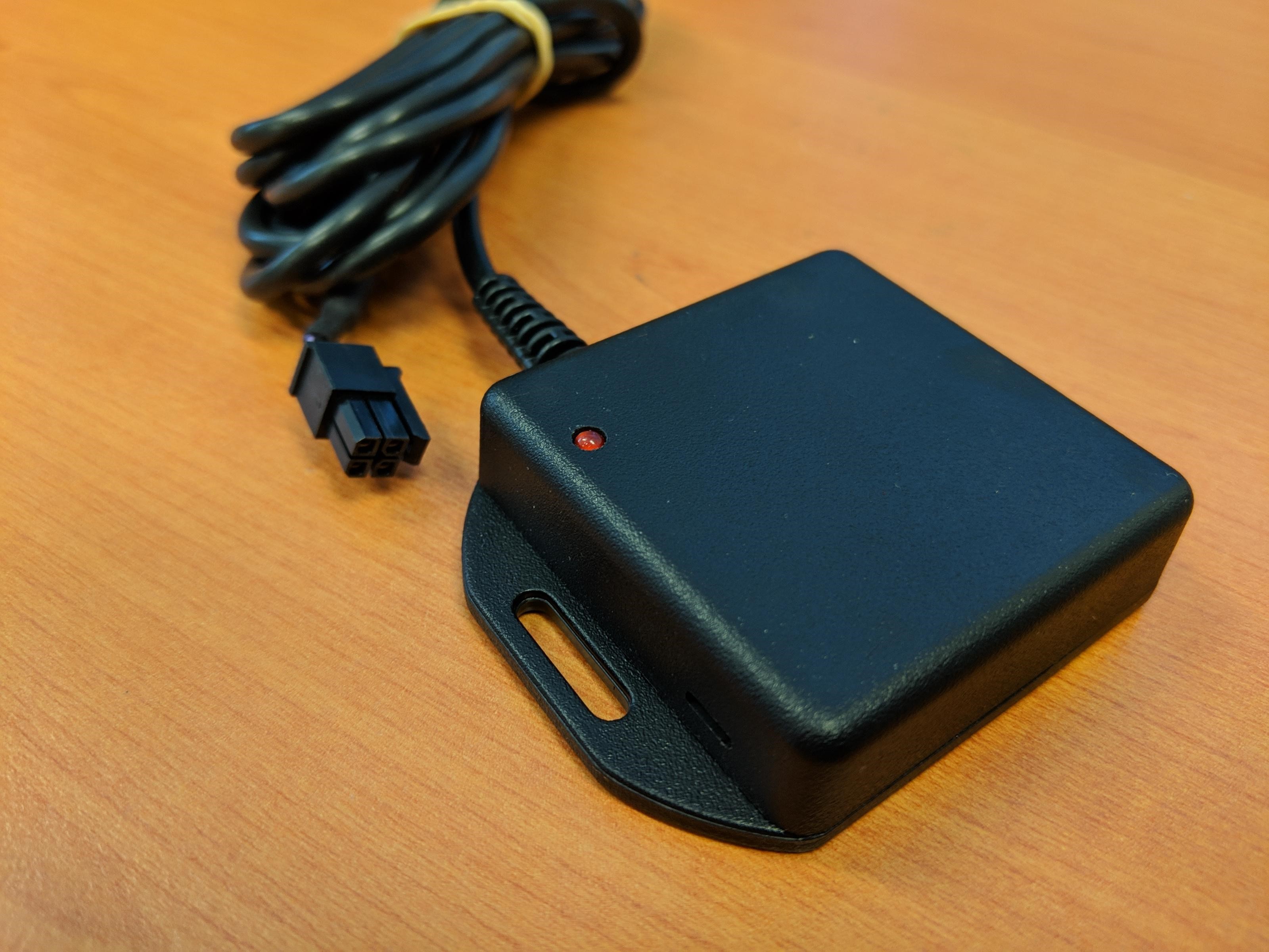
In the Box
You'll get a compact box containing the G120 and a 24 wire harness.
Setting it Up
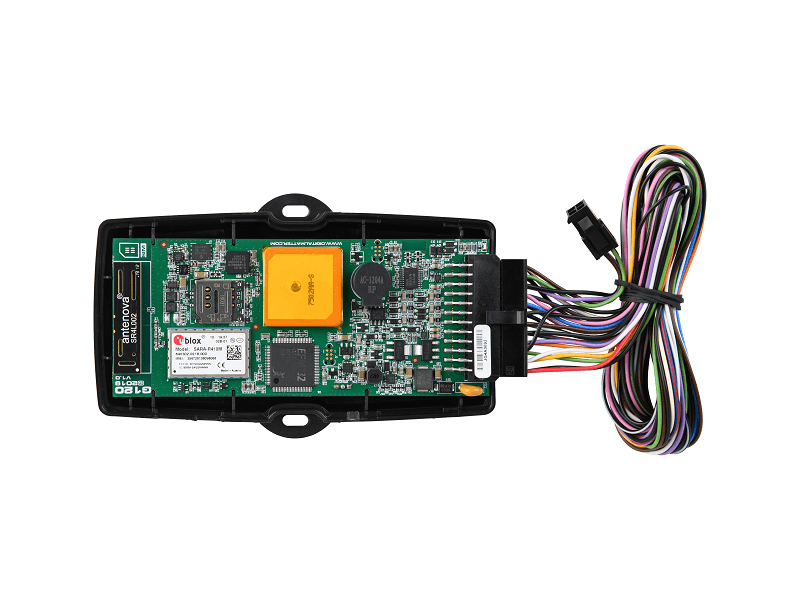
SIM Card
The G120 takes the Micro 3FF SIM card. The SIM holder is on top of the main board, between the modem and GPS antennas. When handling the G120 take care not to touch the GPS antenna, to minimise the risk of damaging the sensitive GPS amplifiers with static discharge.
- Ensure the battery and external power are disconnected to ensure the mobile data connection is not active.
- The SIM holder is hinged - slide to unlock as marked on the holder.
- There is a small etching on the SIM holder indicating the direction keyed corner should face - the SIM contacts should face down.
To easily get up and running:
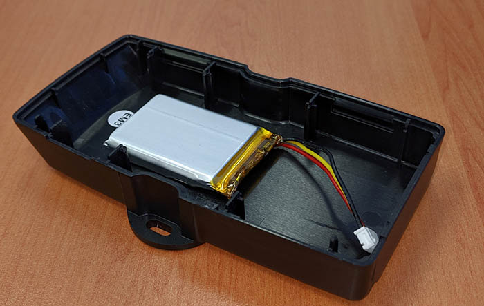
Battery
The battery should be ixed to the lower half of the housing and is a LiPO 1100MHz battery pack. Do not move it. The battery plug is a three-way connector on the underside of the PCB.
- Tilt the PCB, lifting it out of the housing. Raise the edge opposite to the SIM card. Take care to avoid touching the GPS antenna.
- Insert the battery plug into the connector. It should only be possible in one orientation.
- The LED on the board will light up and flash if the battery has sufficient charge. Batteries are supplied fully charged.
- Place the PCB back into the housing. See the next section for more details
Housing Assembly
Once the SIM and batteries are installed and the device is online, the housing can be closed. The lid of the housing clips into the base. No screws are required. To close the housing, line up the top and bottom parts. Push the housing together firmly.
- Locate the PCB on the base. There are a number of fingers around the edge of the PCB that will locate it.
- Place the lid on the base, and gently squeeze one side to engage the clips.
- Squeeze the other side to engage the remaining clips.
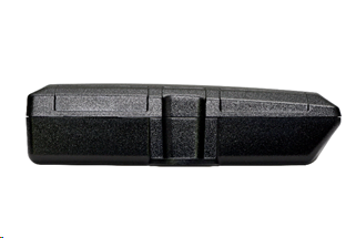
The housing can be opened by prying the lid from the base using a flat screw driver. A wide screw driver will ensure the housing is not marked.
- Locate the slot for the screw driver on the side of the housing.
- Insert the screw driver and twist to pry the housing apart. Be careful with the clips.

Device Installation
The housing has mounting holes for screws, bolts or cable ties. There are a few considerations for the final mounting position of DM devices. The devices have been engineered to have the best possible GPS reception. It will work from inside engine bays, body panels, under dashboards and other places where other GPS devices simply fail to operate reliably. Although the units will work in these locations it is always advisable to install them where it is best able to get signals from the GPS satellites, with the optimum position being a location with a clear 180-degree view of the sky
Note
The Dart, Dart2, G62 LTE & LoRaWAN and G100/G120 models all have 200mA fuses installed on the PCB for external power inputs. Digital inputs (including ignition) and switched ground outputs do not have integrated fuses, and are not specifically required by design, but may be installed to protect against external wiring faults.
The Fuses are self-resetting and do so when the fuse cools down. If the fault that is causing the fuse to trip is still present, it will require the device to be removed from power sources.
This means that the installer does not have to set up their own fuses for the device.
The device is not IP67 rated, so be cautious when installing it in the engine bay or in an exposed location.
Instructions for Mounting
For greater detail on the mounting process, check out the knowledge base article here
Getting Online
The battery should come pre-charged. Once you insert it, the internal LED will come on and flash. If the SIM card works and there is sufficient charge in the battery, the device will connect to the OEM Server.
To confirm it has connected, go to www.oemserver.com/installer and search for the serial number. The LED will flash slowly at first then when it opens a connection to the server it will flash fast. Once data is sent, it will go solid briefly and revert to flashing fast. When the device goes to sleep, the LED will switch off. If the battery is too low, use the harness to provide external power. If the LED flashes but the G120 does not connect, check the SIM is in the holder correctly and check that the SIM is working.
Remember
Make sure once you're online, to declare your APN in the Admin parameters to ensure if you lose the network connection the device knows where to re-connect, and doesnt take time and battery life scanning through all known frequencies
APN AutoNet
For more information on Declaring APNs and the 4G AutoNet, see our knowledge base article here
Troubleshooting Steps
Default Parameters
Default Settings
The G120 will operate with default settings out of the box. These can be changed using the OEM Admin interface. The defaults include:
Default I/O Mappings
Digital inputs, analogue inputs, and various 'statuses' (e.g. GPS interference detected) can be mapped to device Digital inputs
The G120 has the following digital inputs mapped by default, it is important to keep these in mind when mapping inputs to avoid clashes.
Digital Inputs
| Digital Mapping # | Name |
|---|---|
| 0 | Ignition |
| 1 | Digital Input 1 |
| 2 | Digital Input 2 |
| 3 | Digital Input 3 |
| 4 | Digital Input 4 |
| 5 | GPS Interference Detected |
| 8 | GPS Jamming Detected |
Status Flags
DM Device use "Digital Status Flags" contained in the Digital Input data field. In Telematics Guru - they are repackaged and mapped to Digital Inputs, as indicted below.
| Status flags | Name | Digital Input in TG |
|---|---|---|
| bit 0 | Trip Status | 24 |
| bit 1 | Battery Good Flag | 25 |
| bit 2 | External Power Good Flag | 26 |
| bit 3 | Connected to Server | 27 |
Analogue Inputs
| Analogue Mapping # | Name |
|---|---|
| 1 | Supply Voltage |
| 2 | External Voltage |
| 3 | Internal Temperature |
| 4 | Cellular Signal Strength |
| 6 | Analogue Input 1 |
| 7 | Analogue Input 2 |
Harness Definition
The harness is a 24 way Molex connector which plugs into the board.
Harness Definition
For the full harness definition - see G120 Harness Definition
Bluetooth Tracking
Bluetooth
For information on setting up the G120 for Bluetooth scanning - see here
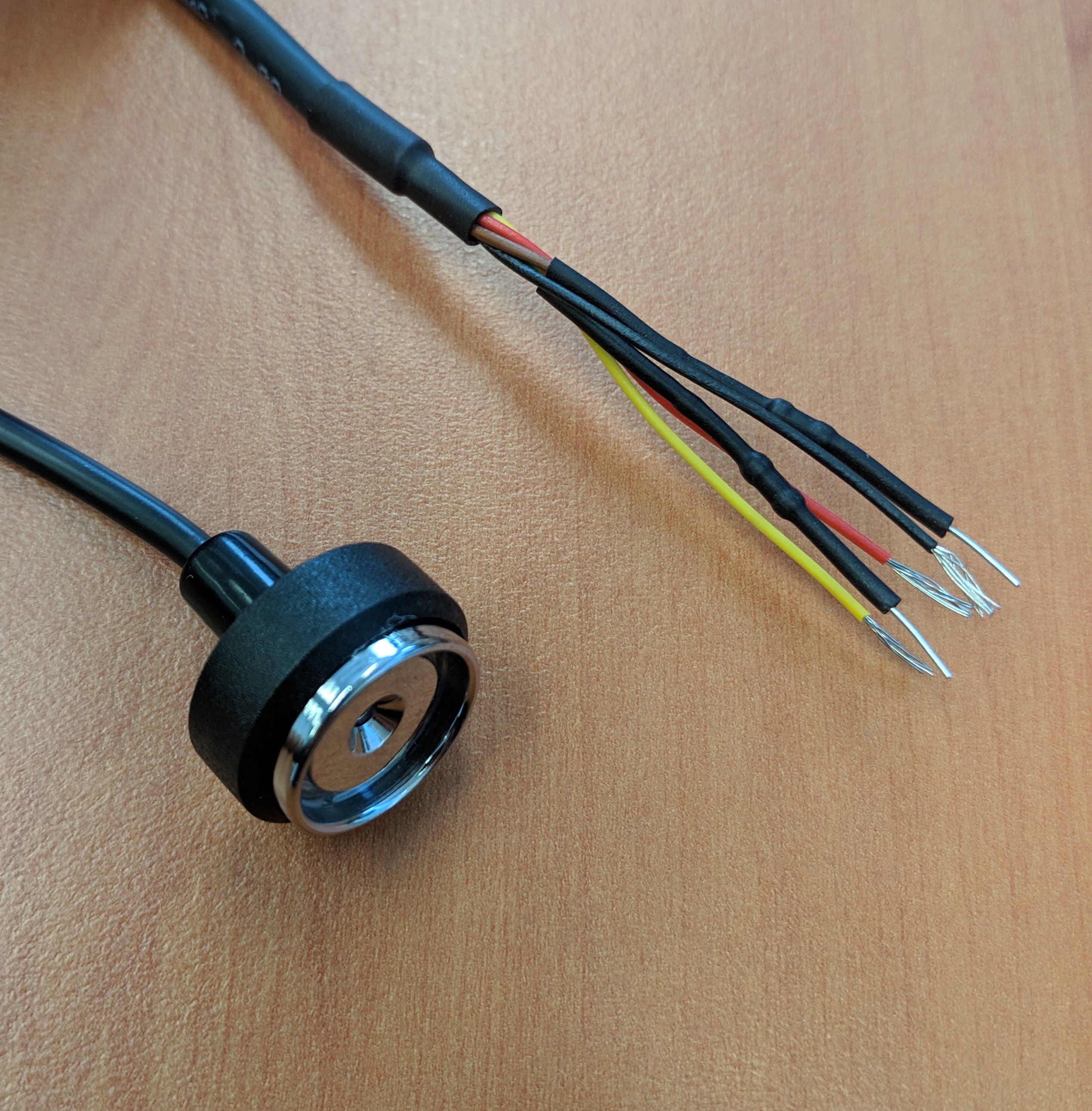
Driver ID
Driver ID
The G120 can read Driver ID tags from the following reader types:
 |
 |