Analogue Input (Advanced)
How to use the Advanced System Parameter Tab for Analogue Input on a hardwired device

Written by Matthew Clark-Massera
Updated at September 10th, 2025
Table of Contents
Advanced System Parameters: Analogue Input
Applicability:
| Device | Analogue Input Range | Analogue Input Pin |
|---|---|---|
| Arrow Global Bluetooth® | 0-30V | 8-wire harness, this is the Green wire. |
| Dart3-2G, Dart3-4G, Dart3-4G Bluetooth®, Dart3 Global Bluetooth® | 0-40V | 12-wire harness, this is the Orange/White wire, pin 6 |
| G120-2G and G120-4G | 0-30V | 24-Wire harness, this is the Orange/White wire, pin 1 |
| G70-2G, G70-4G, G70-4G Bluetooth® | 0-40V | 10-wire harness, this is the yellow wire. |
| Hawk | For the Hawk, see Hawk - Configure Analogue Input | |
Key Points
- The inputs are accurate to within approximately 100mV (0.1V).
- The analogue input simply measures the voltage at the input.
- Generally, this voltage comes from a sensor, where the voltage is proportional to the sensor reading.
Examples of applications include:
| Fuel Level/Tank Level Monitoring | Often an asset's fuel gauge will have a voltage output. The voltage seen is proportional to the fuel level. |
| 0-5V Analogue Sensors |
Many sensors exist which output a voltage, i.e. 0V is the bottom of the range, and 5V is the top. These can be connected with no integration required. The sensor's range will need to be reviewed. If it has a large range, i.e. -70°C = 0V and 380°C = 5V, the analogue input may not be accurate enough. |
| 4-20mA Sensors |
The 4-20mA (current) signal can be converted into a voltage via a sense resistor. Meaning these types of sensors can be read. Please note that analogue input draws current and can affect the reading. If high |
Wiring
Connect the Analogue Input wire to the positive of your monitoring target.
Configuration
To simply report the voltage seen at the input to the server, no special configuration is required. The below is default, and the analogue input is mapped to Analogue Input 5 by default.
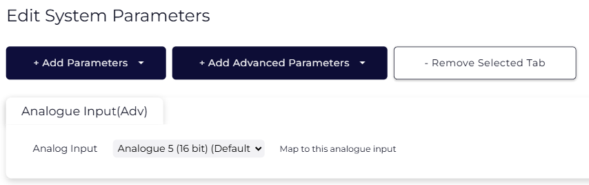
If the above is configured, the voltage at the input will simply be read approximately every 200ms while awake. However, there are no special log upload triggers based on the analogue input alone. Instead, when other conditions on the device necessitate a log, the most recent analogue input value at the time of other logs (i.e. heartbeats, elapsed time, start of trip, heading change during trip) will simply be uploaded. In this case, the value will be present within the payload under analogue 5.
This means that the value is updated with each heartbeat when out of trip (default: 60 mins) and about every 60 sec when in trip.
Integration Notes
Please be aware that the message payload will only contain mV values, and all conversions must be conducted on the other side of your Connector. For example, in Telematics Guru, analogue conversions are done on the I/O mappings tab for an asset.
Analogue Threshold Parameters
Applies to Arrow Global Bluetooth®, Dart3 series & G70 series only
For some applications, we may want different upload behaviour compared to what is described above. For example:
- To save data/cost, scale back in trip logs + heartbeats, and force an upload if we breach the threshold at any time (rather than waiting for the next heartbeat)
- Upload if the fuel/tank level is dropping too quickly, and keep uploading regularly until it gets back to normal.
To fit use cases such as these we can configure the analogue threshold.
Example: Alert when Generator Voltage dips below 18V
- We are monitoring a generator, which our device is connected to. The Dart3 or G70 external power (red and black) is wired to the generator.
- The generator both powers the Arrow Global BLE, Dart3 or G70, but this external voltage is also what we are interested in measuring
- To save data costs, and platform fees, the heartbeat has been scaled back to once daily, and in trip uploads disabled.
- We want to be notified if the generator voltage dips below 18V, as this means it requires attention.
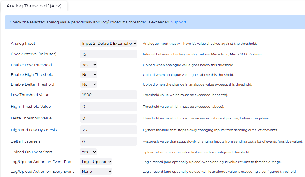
The image above shows settings to fit the use case.
| Analog Input | Analog input 2 is the input used for Vext |
| Check Interval | Sample the input every 1 min to check for changes |
| Enable Low Threshold | We are configuring a lower bound threshold for an alert when we dip below 18V Analog input 2 is the input used for Vext |
| Low Threshold Value | 1800 = 18V |
| High and Low Hysteresis |
25 means that if the voltage dips below 18V, the threshold is breached, but it has to return back to above 18.25V to reset. This stops multiple alerts going off if the asset hovers about the threshold - i.e. flicks between 17.99V and 18.01V
the inputs are only accurate to within approximately 100mV (0.1V) - so configure a hysteresis value above this. |
| Upload on Event Start | Yes = Upload as soon as we dip below 18V |
| Action on Event End | When we return back to 18.25V (back to threshold range) - upload again. |