Configuring 4-20mA sensor readings on the Hawk

Written by Matthew Clark-Massera
Updated at March 12th, 2025
Table of Contents
The 4-20mA interface is common for industrial sensors. Such sensors output an amperage between 4mA and 20mA proportional to the signal (pressure, temperature, moisture, vibration) they are measuring.
Wiring
The wiring of 4-20mA sensors differs depending on the specific sensor, and depending on the specific card you are using.
Agtech1, RS1 and Bluetooth+ Card
To properly use a 4-20mA sensor with the Hawk, you need to wire it sensor into:
- A 4-20mA input on the Hawk card.
- The Vboost or 3v3 Switch Power on the Hawk Card
- GND (on the baseboard)
For details on different cards IOs, please see this article.
When using the Ag-Tech1 plug-in card, the I/Os of interest are:
| Function | Agtech1 IO | RS-1 IO | Bluetooth+ IO |
| VBoost | 2 | 2 | 8 |
| 3.3V output | 5 | 5 | 7 |
| 4-20mA | 9 | 9 | 1 |
4-20mA sensors typically come with 3 wires, and the below connections should be made:
| 4-20mA Sensor Line | Connection |
| VCC (Voltage Input - usually 3V3 or 5V) |
|
| GND | Connect to Hawk GND |
| 4-20mA Signal Line | Connect to 4-20mA input |
For 2 wire connections, the 4-20mA Signal line acts as the GND.
For 2 wire configurations, the VCC cable should be wired into 3v3 or Vboost, and the 4-20mA signal line into the 4-20mA input.
4-20mA Card
4-20mA sensors typically come with 3 wires, and for the 4-20mA Card, the below connections should be made:
| 4-20mA Sensor Line | Connection |
| VCC (Voltage Input - usually 3V3 or 5V) |
|
| 4-20mA - (GND) | Connect to 4-20mA - |
| 4-20mA + (Signal line) | Connect to 4-20mA + |
Configuration
We now need to configure the Hawk to
- Wake up on a schedule to take a reading - (Set up a Task)
- Power on the sensor at the correct voltage (via the Vboost or 3V3 rail)
- Sample the sensor after some time (warm up delay)
- Log the reading and optionally upload.
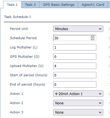
Configure Task
Configure a task at your chosen frequency - choosing 4-20mA Action 1 as an action.
Example: Configure Ag-Tech1 parameters
3V3 Sensor
If we have a 3V3 Sensor, we configure the 3V3 rail to be powered when the 4-20mA Action is done.

5V or 12V Sensor
If we have a 5V/12V sensor, we set the Vboost rail to be activated when doing a 4-20mA action.
We can set the Vboost Output Voltage Level to 5V or 12V

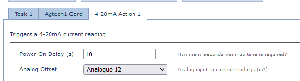
4-20mA parameters
Set the power on delay and the Analogue which the reading should be mapped to.
Reading Conversion
The reading is reported in µA - divide by 1000 to get to mA
i.e. a reading of 4250 seen in the data = 4.250mA
Reading Resolution and Accuracy
4-20mA Card
12 bit resolution.
Full scale is 0-22mA.
Each step size is ~5.37 μA
Readings are typically ~2% accurate
Other Cards
12 bit resolution.
Full scale is 0-33mA.
Each step size is ~8.06 μA
Readings are typically ~2% accurate