Tip Detection and Rotation Counting
Table of Contents
Tip Detection and Rotation Counting are supported by our battery powered devices.
- The tip event is useful for detecting the emptying of containers such as skip bins and detecting when equipment has been knocked over.
- The rotation counting is useful for recording the uncoiling of cable drums.
When enabled, the device's accelerometer will detect Tip and Rotation events exceeding angle thresholds in a particular Axis (X, Y or Z) and log a record containing:
- Log Reason 9 - 'Digital Input Changed'
- Record Time
- Last known GPS time and position (FID 0)
- Tip Count (Configurable Analogue Input)
- Rotation Count (Configurable Analogue Input)
- Current Angle (Configurable Analogue Input)
Since the immediate record contains only the last known GPS position, the Tip Event Action can be configured to attempt a GPS fix after each Tip event. To get the actual location of the tip.
It can also be configured to attempt an upload with the result of the fix once, or to continue retrying the fix/upload until the device succeeds, with increasing back-off timeouts in the event of failure.
Measuring Angles
The angles used by the Tip Detection feature are measured around a chosen axis according to the right-hand rule.
The device axes are arranged with X and Y in the plane of the circuit board, and the Z axis pointing out from the device towards the user.

When the device rotates in space, its coordinate system rotates with it. The angle it reports is the angle of 'down' relative to the chosen axis. For instance, if the device is balancing upright, and you have chosen the Z axis, the angle readout will be 270° (bottom left of diagram below). If you then grab it and rotate your wrist clockwise 45°, the angle readout will become 315° (bottom center).
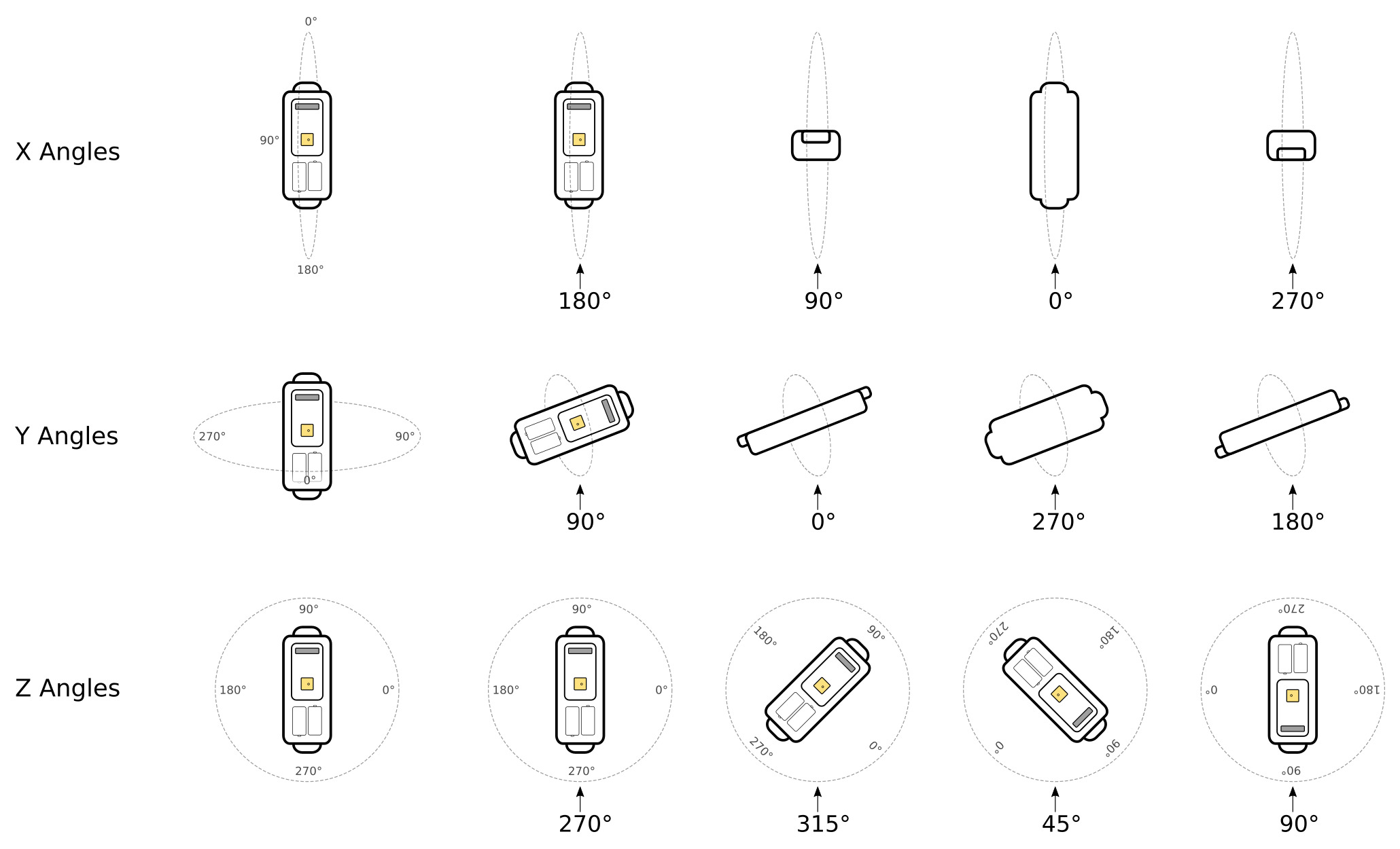
Tip Detection
The Tip Detection feature allows you to define a range of angles that constitute a 'tipped' state. Every time the device enters this range, it will set a digital input, and increment an analog counter. It can also optionally log a record, perform a GPS fix or upload data.
The tip range defines a sector of a circle around the chosen axis.
- In the examples below, the Z axis has been chosen.
- By changing the order of the minimum and maximum angles, you can choose for either the larger or smaller area of the circle to be the 'tipped' range.
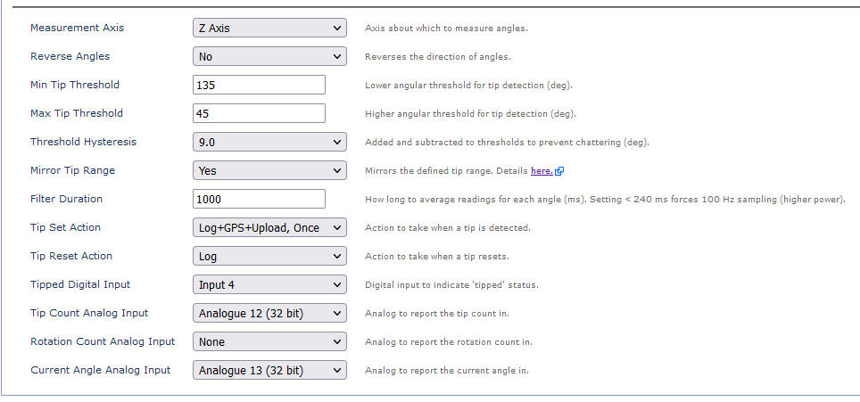
- By selecting the Mirror option, you can have two ranges (useful for 90° tips, and if the device might be installed upside-down).
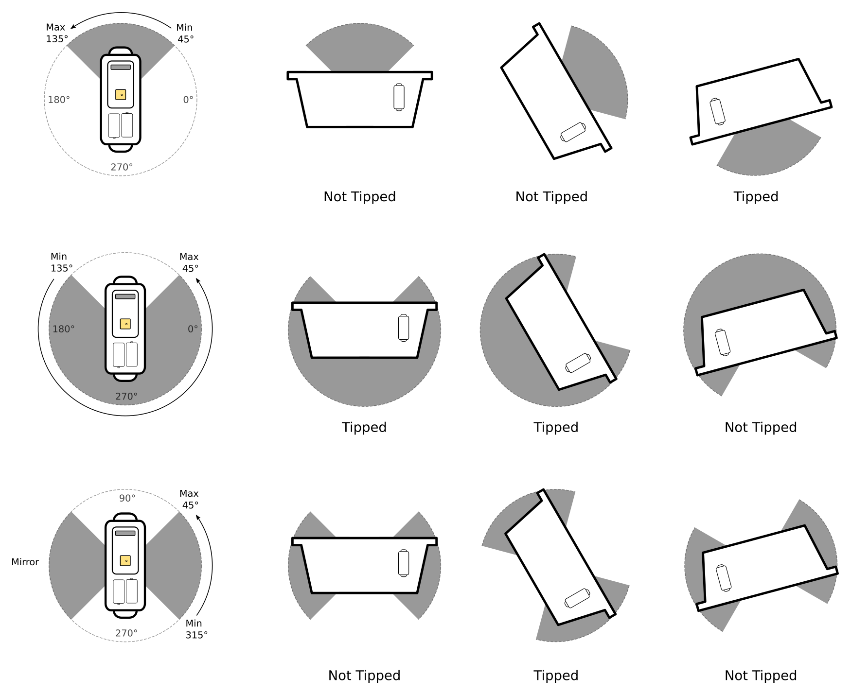
Configuring Tip Detection:
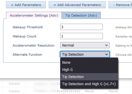
1. Set Accelerometer Function under Accelerometer Settings
Add the Accelerometer Settings Tab, configure the Alternate Function (Tip or Tip + High G)
2. Configure Tip Settings
Configurations for the options in the image above are shown here:
1. Min 45° to Max 135°

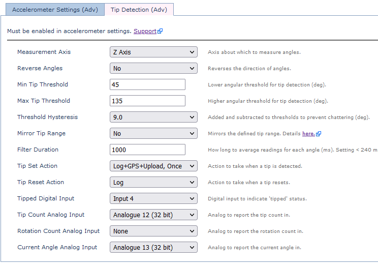
2. Min 135° to Max 45

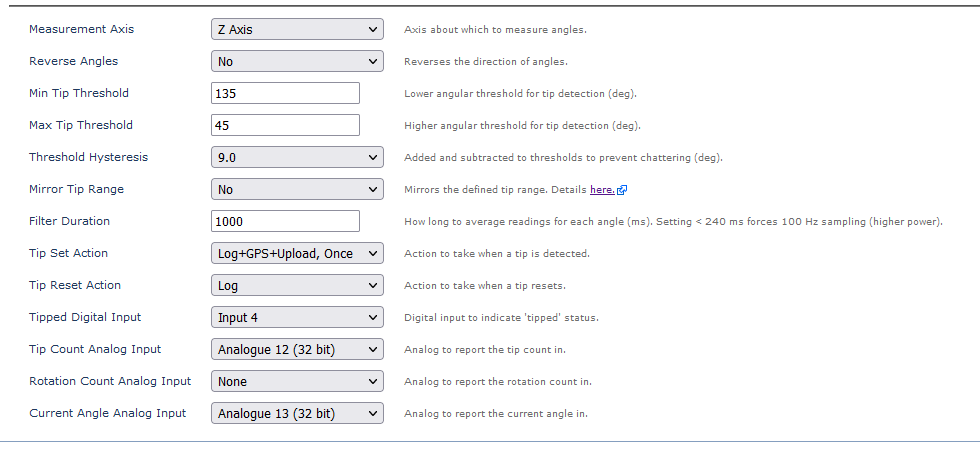
3. Min 45° to Max 315, Mirrored

Rotation Counting
The Rotation Counting feature allows you to record the number of rotations about the chosen axis. When the rotation count is mapped to an analog, the device will keep track of rotations in both directions. The rotation count analog will give the number of whole rotations, and the current angle will give the fractional rotations.
Like the tip count, the rotation count starts at zero, reaches a maximum of 32767, and then wraps back to zero. However unlike the tip count, the rotation count can go backwards, wrapping from zero back to 32767. You can control which direction is considered positive and which is negative using the Reverse Angles parameter.
Like the tip count, the rotation count will not reset to zero except when wrapping, so you must use the change to calculate the number of rotations since installation.
There are three important limitations to keep in mind when using the Rotation Counting feature:
- When the feature is active, the device should not be allowed to lie flat (ie. circuit board should not be parallel to the ground). This orientation makes the angle undefined, and may increase power consumption and drain the batteries.
- The device must be installed close to the axis of rotation, so that it isn't subject to large centrifugal forces. Centrifugal forces confuse the accelerometer, by swamping out the force of gravity.
- The Filter Duration parameter must be set low enough for the reported angle to keep up with the rotations. If it is set too high (or unreasonably low), the rotation count won't be accurate.
The centrifugal forces are very sensitive to the maximum RPM of the rotation, and less sensitive to the distance from the axis. The maximum distance you can mount the accelerometer from the axis of rotation is 18 / f2 cm:
Max Speed (Hz) |
0.1 | 0.25 | 0.5 | 1 | 1.5 |
Max Speed (RPM) |
6 | 15 | 30 | 60 | 90 |
Max Filter (ms) |
2400 | 960 | 480 | 240 | 160 |
Max Distance (cm) |
1800 | 280 | 72 | 18 | 8 |
The Filter Duration can be set to the maximum value from the table, or as low as a third of that value for faster settling.
Filter Duration
The filter duration operates as a moving average filter, which allows the device to update even before the specified duration has elapsed. Frequent transitions in and out of the tip thresholds within a 10-second filter duration can result in multiple logs.
To minimize excessive logging, we recommend experimenting with a wider hysteresis value rather than adjusting the filter duration.
Configuration:
Simply configure the analog to report the count in

The Reverse Angles parameter can be used to set the rotation direction.
- Reverse Angles = No - Anti Clock-wise is the 'positive' direction of rotation
- Reverse Angles = Yes - Clock-wise is the positive direction of rotation
Alerts + Displaying the Data on the Server
3rd Party Platforms
Depending on configuration, data is reported to the server on a tip or rotation event.
- Log Reason 9 - 'Digital Input Changed'
- The server can then look for the status of the 'Tip' digital input to determine if we have tipped (0 → 1) or reset (1 → 0)
- Record Time
- Last known GPS time and position (FID 0)
- Tip Count (Configurable Analogue Input)
- Rotation Count (Configurable Analogue Input)
- Current Angle (Configurable Analogue Input)
Telematics Guru
Configure I/O Mappings
If we have configured the Tip Digital Input to DI 4 - it is useful to name it this in TG so it's more human-readable. Edit the asset, and configure I/O mappings.
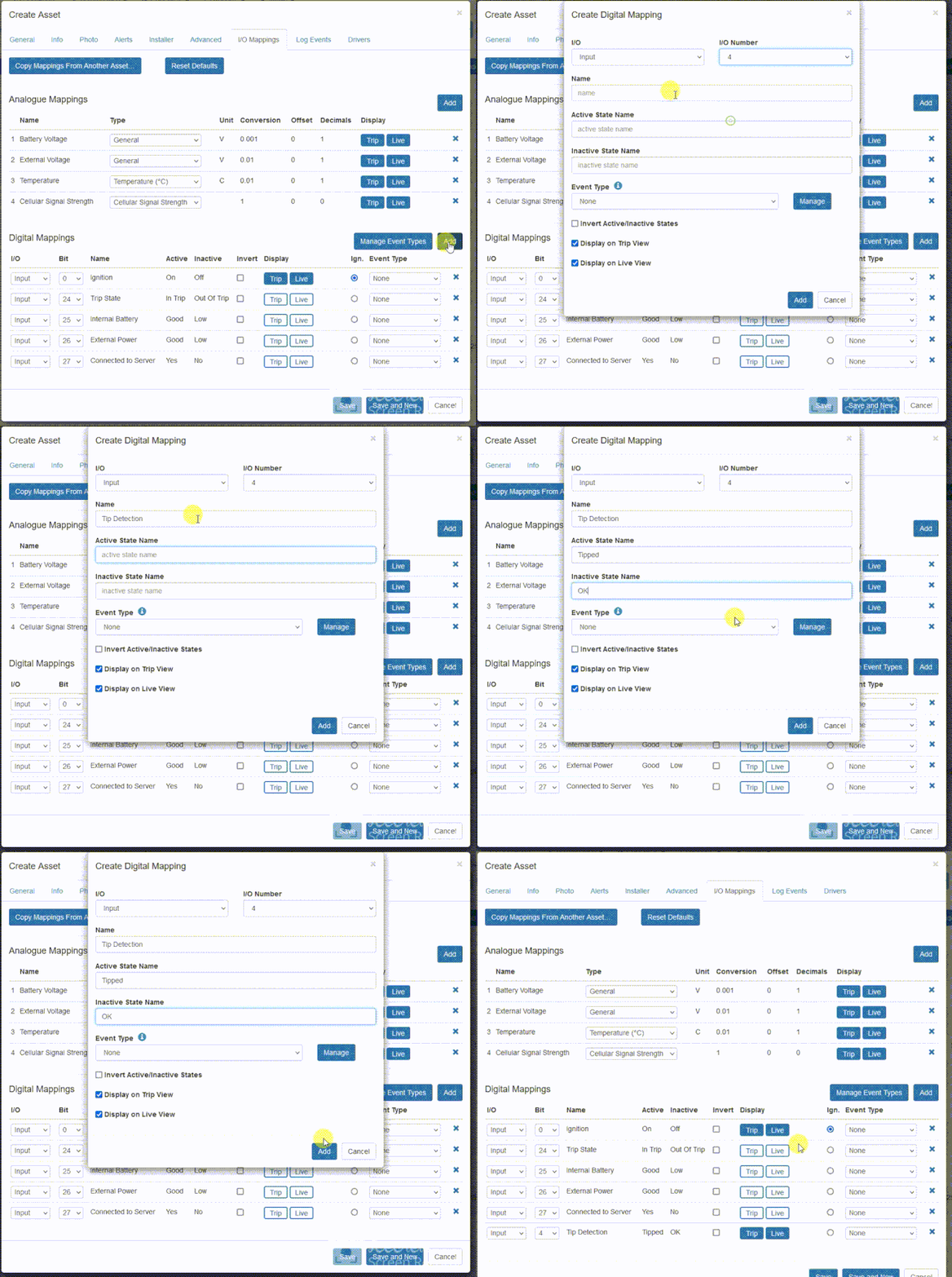
- We can set to display the status on the live and trip views
- We can map this I/O to an event to record all instances of the tip occuring.
- We can do the same with the Tip or Rotation count Analogue Inputs to view the current count on the live/trip views.
Alert
See how to set up an alert here.
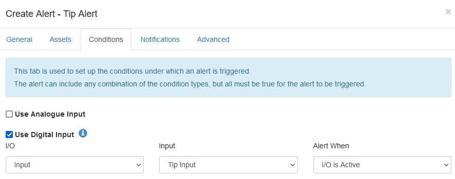
Ensure to give the alert a name and message in the General Tab; apply the alert to the relevant assets in the Assets Tab, and select who TG should send the alert to under Notifications.
In the Conditions tab, select 'Use Digital Input' and select the input you've configured as the tip Digital Input
Timeline View
The Asset Timeline history view, will show a history of these alerts/events (below is a High-G example)

Event Detail/Summary Report
Once an event is created, we can run the Event Detail or Event Summary reports.
- Event Summary Report will display a summary (count) of tip events over a time period
- The Event Detail report will show each tip event (start + end time and duration)
Using Tip Detection for Tamper Detect
Many battery powered devices (e.g. Barra, Manta, Remora ranges) offer a magnetic tamper detection feature - where an alert is set out when a magnet detaches from the device.
It may be tempting to use the Tip Detection feature as a replacement. Unfortunately, we do not recommend using tip detection as a viable solution to detect tamper events. Here are the main reasons:
Excessive Battery Drain
The device has to constantly be awake, checking the accelerometer to scan for tip events. This becomes worse when the device is in trip (where the accelerometer is constantly firing). For example, the Oyster3 with tip detection enabled with 10 hour trips every day would not last more than 6 months.
False Alerts
The orientation is determined purely based on forces measured by the accelerometer. Gravity or movement can impact this. For example a trailer going up a steep hill would constantly report that the devices is being tampered. It would be impossible to distinguish actual tamper events from false tamper events.
Tip Detection only works in 1-axis
Example. Tip Detection is set up using the X axis. If someone removes the tracker carefully and moves the devices in the Y/Z axis only, the device will not report a tip event.
Orientation Detection is an alternate option.
