Digital Outputs - Introduction
How to use the Digital Output 1 System Parameter

Written by Cameron Everett
Updated at August 25th, 2025
Table of Contents
Switched Ground Outputs
Hardwired Digital Matter devices have switched ground outputs which provide a path to ground when 'on' (i.e. allow a path for current, closing the circuit) and are high impedance when off (breaking the circuit). This is an example of a low-side switch.
When the SWGND is active it is a GND.
When SWGND is inactive it is an open circuit.
With the exception of the the Arrow Global BLE, which provides 1 x Switched Ground Digital Output only, our devices offer 2 x different digital output options.
These are:
| Switched Ground Output | Most common and widely used for most applications |
| Switched Power Out | Can be used for some specialist applications |
Applicability
| Device | Output type (Wire Colour) | Harness Definition Link | Firmware Version |
|---|---|---|---|
| Arrow Global BLE | Switched Ground (Yellow) - 2A Max | 8-wire harness | All Versions |
| Dart3-2G and Dart3-4G/Bluetooth |
Switched Ground (Yellow) - 2A Max Switched Power (Purple) - 3-5V 500mA Max |
12-way harness | All Versions |
| G120-2G and G120-4G |
2x Switched Ground (Green and Yellow) - 2A Max Switched Power (Orange)
|
24-Wire harness | All Versions |
| G150-Global |
2x Switched Ground (Green on Harness 1 and Grey on Harness 2) - 2A Max Switched Power (Brown on Harness 2)
|
2x10-core harnesses | All Versions |
| G70-2G and G70-4G | Switched Ground (Green) - 2A Max | 10-core harness | All Versions |
| Hawk IoT Datalogger | The output type is specific to each specific Hawk card. | Card I/O Spec | Card I/O Spec |
Digital Output 1 Tab Setup

See below for the different options which can be chosen for Function:
None
The Switched Ground Output is disabled
Digital Output
Digital Outputs can be used for remote switching. e.g. to turn on or off a pump or lighting tower.
Any outputs set up with the Function "Digital Output" can similarly be controlled by sending an asynchronous message to control outputs.
Buzzer
When buzzing should happen (e.g. if no driver ID is scanned) the output will pulse on and off to correctly generate sounds from a connected buzzer unit.
Immobilizer
The digital output will control an immobilizer if wired correctly and having the Function set to Immobilizer. Immobilizers are referenced in other system parameters, like Driver ID or Input Monitor. One other application is that a vehicle can be immobilized by sending a command from the server (see Driver ID & Async Immobilization Methods with Powered Devices). Digital Matter's own IoT platform - Telematics Guru has an 'immobilize' button, which causes a message to be sent down to the device to turn any outputs set up with the function "Immobilizer" on or off. This same message can be sent from any 3rd party server using the OEM WebAPI - contact Digital Matter Support for documentation.
Active High
The active level setting depends on the function. This can be used to invert the output. LED's and buzzers should generally be Active High ‘Yes’ and Immobilizers Active High ‘No’.
Switched Power Out
When this output is ON, a voltage is supplied - it ranges from 3-12V depending on the device model. So, this could be connected to the positive terminal of such a peripheral.
Parameters are the same as for Switched Ground outputs. Set the Function to determine what causes the output to turn on or off.
Remote Switching Latency
It is important to note that all of our devices (even hard-wired vehicle trackers) will sleep during periods of inactivity. For example, using the default tracking parameters for our powered devices; heartbeats happen hourly when the ignition is off while the asset is stationary. Between heartbeats, the device will sleep and the cellular modem will be off.
This means that a command sent down to the device will not be received until the next heartbeat, when the device next connects.
If we require low latency output switching, to improve upon this, we can set this parameter under the upload settings, available on hard-wired devices.
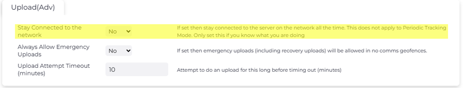
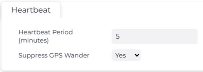
This will cause the device to attempt to remain connected to the network all the time. In practice, generally, the network will kill the connection after 5-10 minutes. So the device additionally needs to be set to upload often enough to keep the connection alive. This can be done by setting the heartbeat interval to a sufficiently short window (may require some experimenting)
This will allow commands to toggle outputs to be received by the device within 60 seconds in most cases. It should be noted that this functionality was not designed with live control applications in mind.