RS232 Passthrough Mode
Table of Contents
The G120 & G150 are capable of acting as an intermediate between a server and an RS232 serial-connected device, passing along data received via an async message from the server, and logging data that is received via RS232 from the third-party device.
This flexible feature is best utilised with a custom-built server that can interpret the data from the third-party device.
The data will be sent in Field 9. Details are covered in the integration documents. Contact DM Support for a copy.
Requirements
The G120 & G150 currently only log data that is terminated with a special character, such as the new line character. This helps prevent erroneous logging and helps synchronise the device's logs with the data sent by the device. If your third party device does not send a character to identify the end of a data line, then contact DM support about integration options.
The serial port of the G120 & G150 is configured as follows:
- Baud Rate: Configurable between 1200 and 115200
- Data Bits: 8
- Stop Bits : 1
- Parity Bits: none
- Flow control: none
Wiring
For RS232 serial integrations the G120/G150 must be connected to the third party device with the following wires:
- Ground (any ground)
- RS232 IN (RX) - Pin 21 (purple) on G120, or Pin 4 of Harness 2 on G150 - ±5V
- RS232 OUT (TX) - Pin 22 (black/white) on G120, or Pin 5 of Harness 2 on G150 - ±5V
Check the G120/G150 Harness definition for more details
Parameters
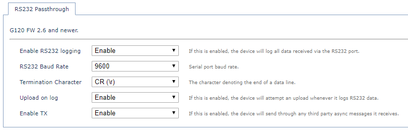
There are two tabs required to set up RS232 passthrough mode. The first is the RS232 function tab:

RS232 Function: This parameter determines which feature is in control of the RS232 port. By default, this is set to Iridium. For this feature, it should be set to "Passthrough".
The second tab required is the RS232 Passthrough tab:

Enable RS232 Logging: To enable the RS232 passthrough feature this must be set to "enable".
RS232 Baud Rate: This is the baud rate for the serial communication. If your required baud rate is not listed, speak to support about the potential for other rates.
Termination Character: This is the character that the third party device appends to all transmissions, signifying the end of a data line. If your required character is not listed, speak to support about the potential for other characters.
Upload on Log: If this is enabled, the G120/G150 will commence an upload whenever it creates a log of data received via the serial port.
Enable TX: If this is enabled, the G120/G150 will forward on any third party data async messages it receives from the server. If this is disabled, the device will reject third party data async messages and transmit functionality to the third party device will be disabled.
Communication from Server to Device
Contact DM Support for documentation on the ASYNC messaging protocol used to send commands to our devices. The OEM Web API can be used to send these commands. Or when using the TCP connector this can be sent directly to the device.
The 3rd Party Data (0x0015) message can be used to send a string to the device.
It is not checked and simply forwarded on.
Acknowledgement
When using the OEM WebAPI - this API will give a 200 OK response if the API call was successful.
This is not a response from the device.
The device will also respond to once it has received the message - but this is handled by OEM unless in the 'direct to 3rd party' integration mode.
Regardless, these ACKs are not of much use - as any message that fits the format will be accepted by the device and blindly passed to the connected device via the RS232 port.
Once received - the connected device would respond - which can then again be read in FID 9 - so this is how you should determine if a message was succesful.
