Telematics Guru Telemetry - Getting Started
Table of Contents
Telemetry
Status Flags are represented in the left most 8 bits
| 31 | 30 | 29 | 28 | 27 | 26 | 25 | 24 |
Recovery Mode Active |
Tamper Alert
(Remoras)
|
External Power Enabled |
Shunting power from battery |
Connected to GSM |
External Power Good |
Internal Battery good |
Trip Status |
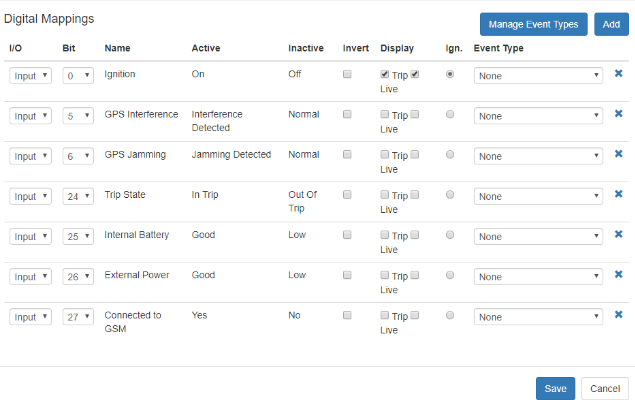
Digital Inputs of the device are represented in the remaining 24 bits, Bits 0, 6 and 6 are commonly set across all devices.

I/O Mappings
The Input/output mappings are set for the individual Assets in Edit Asset, inside the Manage Asset menu. If you compare these value to the grid above, you'll see they all line up.

Example Telemetry
If we take a snapshot of a log's telemetry we can decode the state of the Asset. Note: remember that the bit number reads from right to left, starting at 0.
| Here we have a 1 or 'ON' status flag for bits '0', '5' and status flags '1', '2', '3', '4'. 0000 1111 0000 0000 0000 0000 0010 0001  Bit 0: Ignition = active Bit 5: GPS Interference detected Status Flag 0: Device is 'In Trip' Status Flag 1: Internal battery is 'Good' Status Flag 2: External power is 'Good' Status Flag 3: Connected to GSM network: 'YES' |
