[HAWK] - Configure SDI-12 Readings

Written by Matthew Clark-Massera
Updated at August 25th, 2025
Table of Contents
The SDI-12 interface is a low data rate protocol designed for agricultural and scientific sensors (SDI-12 Website).
A soil moisture probe will often have multiple sensors along its length. Each sensor can have an address between 0 and 9 (inclusive), and allows for up to 10 different 'measurements'. Each of these measurements can actually return a number of different values (up to 15). For example, a soil moisture probe may have a soil moisture and soil temperature measurements, and each of these will return a number of values, each being taken at a certain point along the probe.
All Hawk IO Cards with SDI-12 capabilities are programmed to automatically interface with Measurement (M!) commands from SDI-12 sensors. In addition, from FW v 1.14, the Agtech1 card can also use C! commands.
See "Configure SDI-12 Readings" below for more information. If you need to read alternate measurements from SDI-12 sensors such as Verification commands (V!) please contact Digital Matter support.
What SDI-12 Commands does the Hawk Use?
C! and M!
The Hawk mainly uses the M! command. It is mainly designed around the use-case of monitoring soil moisture probes. Implementing multiple arbitrary commands in a specific sequence generically is more complicated - but contact us if you have specific requirements to discuss the options.
The full control flow of the SDI-12 measurement, for an address a, and measurement type t, is:
Tx: aI! (identify device)
Rx: axxxxx…. The response gets sent as part of the SDI12 data. If no response, then we give up this measurement.
For each measurement parameter, the following goes through each set bit in the mask
Tx: aM! (or aMt! if the type is not 0)
Rx: aXXXn. XXX is how long we need to wait before the samples are ready, and n is how many it will return (both can be 0).
After waiting XXX seconds, the following goes through each value of n, from 0 to 9, until either 0 data is returned (but still a response), or we reach 15 individual values returned. Each aDn command can return more than one value
Tx: aDn
Rx: a<data>
If at any time no response is heard, the measurement is aborted.
Configure SDI-12 Readings
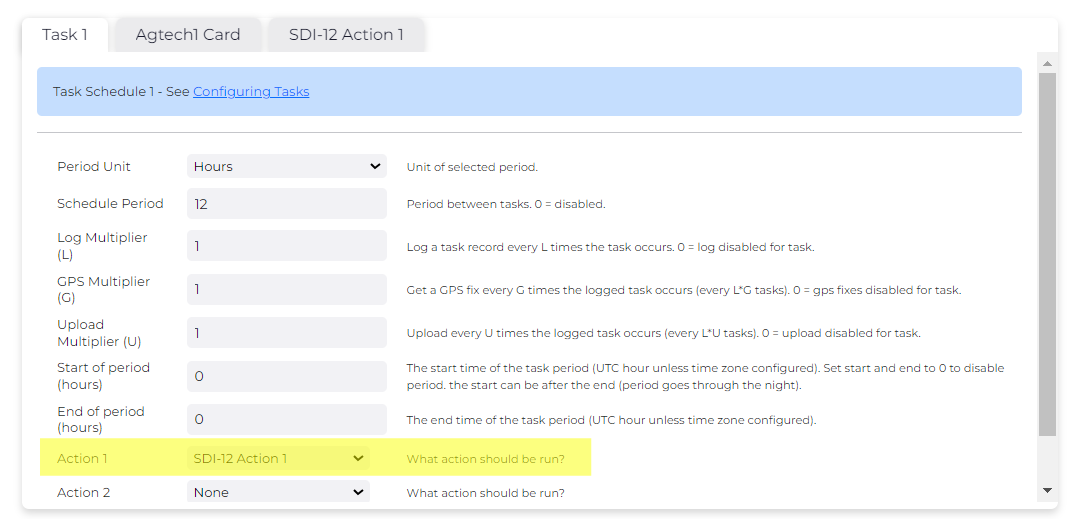
Configure Task
Configure an SDI-12 Action as an action for a task. The below task is for an SDI-12 reading logged + uploaded hourly.
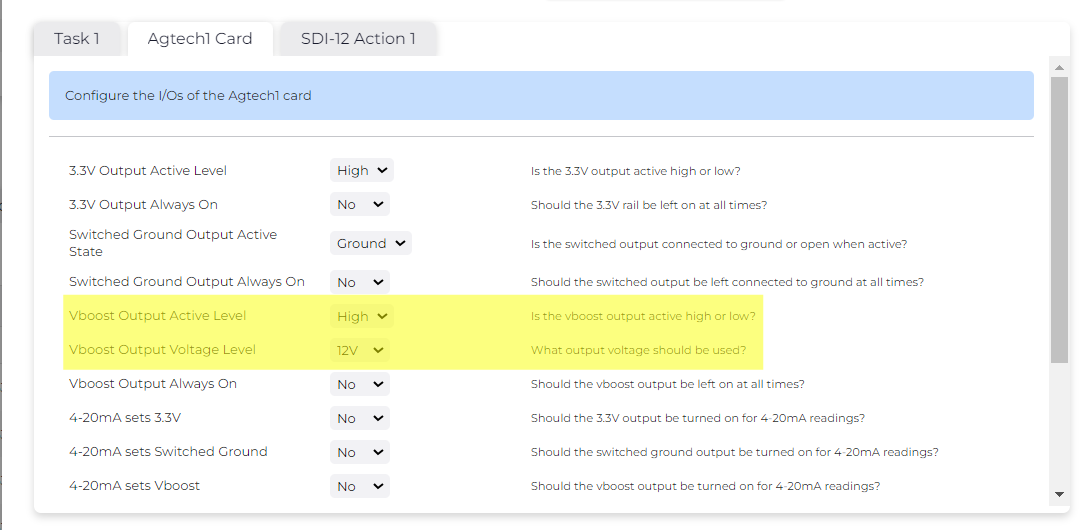
Configure Vboost Voltage Level
While the SDI-12 bus operates at 5V, most SDI-12 probes require 12V to power the sensors.
We need to tell the Hawk to output 12V via the IO Card Vboost output.
Configure SDI-Reading

We specify
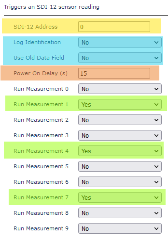
SDI 12 Address
Address of the probe to read - find in the data sheet of the sensor.
Log Identification/Use Old Data Field
SDI-12 data is sent in the following fields. Field 34 is new to the Hawk.
If we only have 1 SDI-12 measurement we are taking, from 1 address, it is not necessary to identify this in the payload. So to save data we can select Log Identification as No.
In general the default Log Identification = No and Use old Data Field = No should be used for most applications.
FID = 4: SDI-12 Device Identification
Length = N + 1
Offset |
Data Type |
Length |
Description |
Unit |
0 |
BYTE |
1 |
Device Address (SDI12 single char address) |
|
1 |
BYTE |
N |
SDI12 Identification string (typically 30 ASCII characters) |
|
FID = 5: SDI-12 Measurement
Length = 1 + N*4
The SDI12 spec allows for a device to support 10 different types of measurements (0-9).
Offset |
Data Type |
Length |
Description |
Unit |
0 |
BYTE |
1 |
SDI12 Measurement Type (0-9) |
|
1 + N*4 |
INT32 |
4 |
Measurement (scaled by 1000) <n data values follow> |
Scaled by 1000 Eg milli-degrees centigrade |
FID = 34: SDI-12 Measurement 2
Length =3 + N * X
This field replaces FID 4 on newer devices.
The SDI12 spec allows for a device to support 10 different types of measurements (0-9).
Offset |
Data Type |
Length |
Description |
Unit |
0 |
BYTE |
1 |
Device Address (SDI12 single char address) |
|
1 |
BYTE |
1 |
SDI12 Measurement Type (0-9) |
|
2 |
BYTE |
1 |
SDI12 Data Format |
0x00 = Scaled by 1000, stored in INT32 Other values are reserved. |
3 |
Dependant on format |
N * X |
N measurements of size X, specified by the format. |
|
Log Identification |
Use Old Data Field |
Fields Sent |
No |
No |
FID 34 |
No |
Yes |
FID 5 |
Yes |
No |
FID 4 + FID 34 |
Yes |
Yes |
FID 4 + FID 5 |
Command Type (C or M)
Defines which command to send to the sensor.
C! commands are only available on Agtech1 FW v1.14+ as of Septemeber 2024.
Plan is to port this functionality to the Agtech2 and Bluetooth Card moving forward.
Please review the Hawk Firmware Release Notes for the appropriate card to see if the functionality is in place.
Power on Delay
Most sensors require some time after power is applied to 'warm-up' or settle down before the reading is taken.
Run Measurement N
Select from the dropdowns which measurements we would like to run
Example
-
Sensor Address 0
-
Use the new data field, with no ID field
-
Power on delay 15 seconds
-
Measurements 1, 4 and 7