Immobilisation Install - Asset can be immobilised from server

Written by Sean Withers
Updated at September 15th, 2025
Table of Contents
Warning!
Digital Matter does not advise connecting an immobilization relay to a safety critical system such as the ignition or fuel pump. A starter motor cut is recommended.
| Device | Firmware Version |
| Arrow Global Bluetooth® | All Versions |
| Dart3-2G, Dart3-4G, Dart3-4G-BLE and Dart3-Global-BLE | All Versions |
| G70-2G, G70-4G and G70-4G-BLE | All Versions |
| G120-2G and G120-4G | All Versions |
| G150-Global | All Versions |
Concept
- Some devices have a switched ground output.
- The SW GND can be wired to a relay, to control the relay
- The relay is also wired to cut/close the starter motor circuit for a vehicle, meaning that whether a vehicle is able to start or not can be controlled by the device
- Immobilisation can be turned on/off by the device based on Driver ID Tag scans, or a command from the server.
Important!
Both features can set up simultaneously, but with one critical exception. If Driver ID tag scans are enabled together with Server-side Immobilisation, only the correct Driver ID will de-immobilise the vehicle. Server-side commands will not de-immobilise the vehicle.
Wiring Configurations
There are different ways to wire in a relay and configure the device settings to achieve a similar result.
However the aim is to try to avoid having the relay coil energized for an extended period of time - so as to not drain the vehicle battery if it is not driven for some time.
Automotive relays will have 2 contacts:
-
Normally Open
- The 'default' state, when the relay is not energized is open (break in circuit)
-
Normally Closed
- The 'default' state, when the relay is not energized is closed (closed loop)
There are 2 common use cases and set ups (this guide covers case 2)
-
Use Case 1: The vehicle cannot be started until the right driver ID tag is scanned.
- In this case when the relay is not energized we want there to be a break in the start motor circuit. So we wire to the Normally Open contact.
- With this config, we can still additionally send a command from the server to immobilize the asset and prevent anyone from starting it, even if they have a valid ID. If one form of immobilization (server command or Driver ID) OR the other is active, the asset can't start.
- In this case when the relay is not energized we want there to be a break in the start motor circuit. So we wire to the Normally Open contact.
-
Use Case 2: Default state is that the vehicle can always be started - unless via Telematics Guru or another software platform an 'immobilize' command is sent.
- In this case we want the relay when not energized to be closed, allowing the vehicle to start. So we wired to the Normally Closed contact. Sending the command will energize the relay.
Setup
Wiring and Installation
Arrow Global Bluetooth
- Connect pin 86 (relay positive) to the Vehicle Positive
- Pins 30 and 87A (normally closed) are wired to form the break in the start motor
- Connect the switched ground (Yellow Wire) to the relay negative, pin 85.
Note
The device will work as normal until the immobilize command is sent to the device from the server. This can be sent from Telematics Guru or a 3rd party platform.
When the immobilize function is activated on the server, the starter motor is cut.
This wiring configuration is used when you want the vehicle to operate as normal until you need to immobilize.

Dart3
- Connect pin 86 (relay positive) to the Vehicle Positive
- Pins 30 and 87A (normally closed) are wired to form the break in the start motor
- Connect the switched ground (Pin 12 - Yellow Wire) to the relay negative, pin 85.
Note
The device will work as normal until the immobilize command is sent to the device from the server. This can be sent from Telematics Guru or a 3rd party platform.
When the immobilize function is activated on the server, the starter motor is cut.
This wiring configuration is used when you want the vehicle to operate as normal until you need to immobilize.

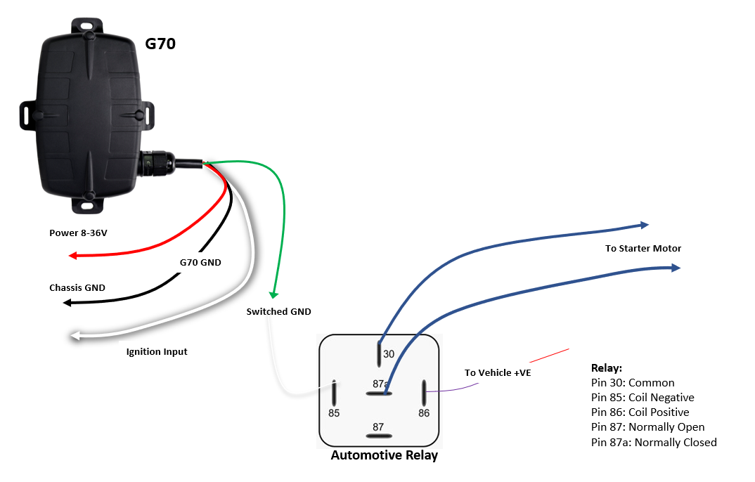
G70
- Connect pin 86 (relay positive) to the Vehicle Positive
- Pins 30 and 87A (normally closed) are wired to form the break in the start motor
- Connect the switched ground (Green) to the relay negative, pin 85.
Note
The device will work as normal until the immobilize command is sent to the device from the server. This can be sent from Telematics Guru or a 3rd party platform.
When the immobilize function is activated on the server, the starter motor is cut. This wiring configuration is used when you want the vehicle to operate as normal until you need to immobilize.
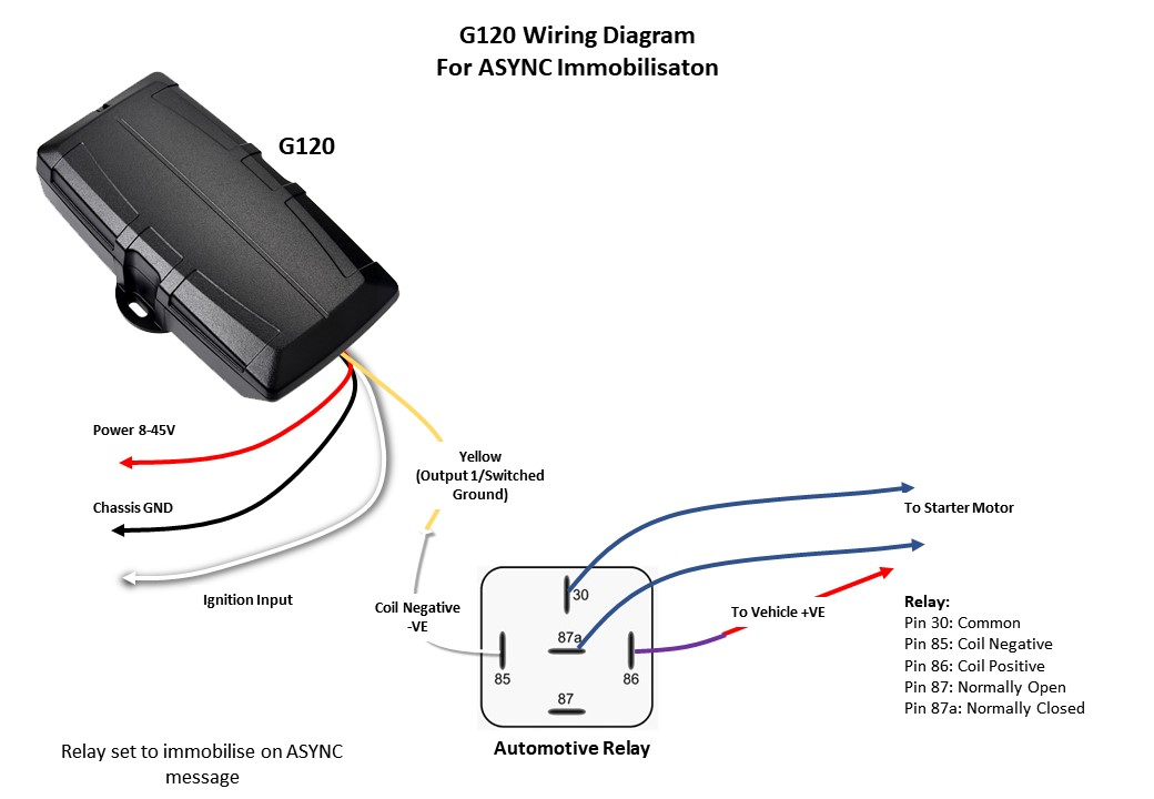
G120
- Connect pin 86 (relay positive) to the Vehicle Positive
- Pins 30 and 87A (normally closed) are wired to form the break in the start motor
- Connect the Switched Ground 1of the G120 (Pin 11) to the relay negative, pin 85.
Note
The device will work as normal until the immobilize command is sent to the device from the server. This can be sent from Telematics Guru or a 3rd party platform.
When the immobilize function is activated on the server, the starter motor is cut. This wiring configuration is used when you want the vehicle to operate as normal until you need to immobilize.
G150
- Connect pin 86 (relay positive) to the Vehicle Positive
- Pins 30 and 87A (normally closed) are wired to form the break in the start motor
- Connect G150's SW GND output 1 (Green wire Pin 8 on Harness 1) to the relay negative, pin 85.
Note
The device will work as normal until the immobilize command is sent to the device from the server. This can be sent from Telematics Guru or a 3rd party platform.
When the immobilize function is activated on the server, the starter motor is cut. This wiring configuration is used when you want the vehicle to operate as normal until you need to immobilize.
Parameters
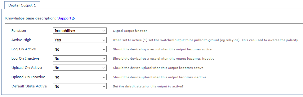
Configure Digital Output 1
We must set that the Yellow wire is to be used for the purpose of immobilisation:
- Add the Digital Output parameter tab
- Function = Immobiliser
- Active High = YES
Sending Immobilisation Command From Server:
Set up Asset in Telematics Guru for Immobilisation
We need to enable immobilisation for the asset in TG
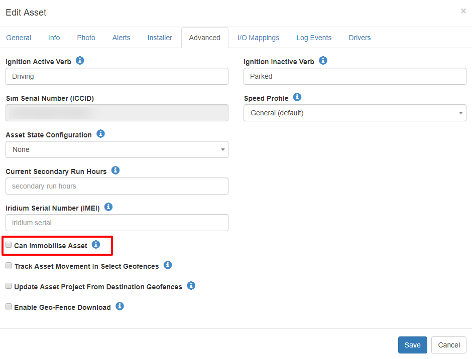
- Edit the asset - Assets → Manage Assets
- Select the Advanced tab in Edit Asset and check 'Can immobilize Asset' as shown below.
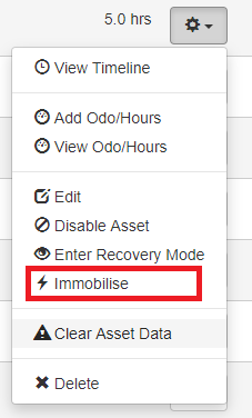
Once a device has been set up to allow immobilization through the edit menu, simply click on the cog menu on the right of the Manage Assets screen, and select Immobilize.
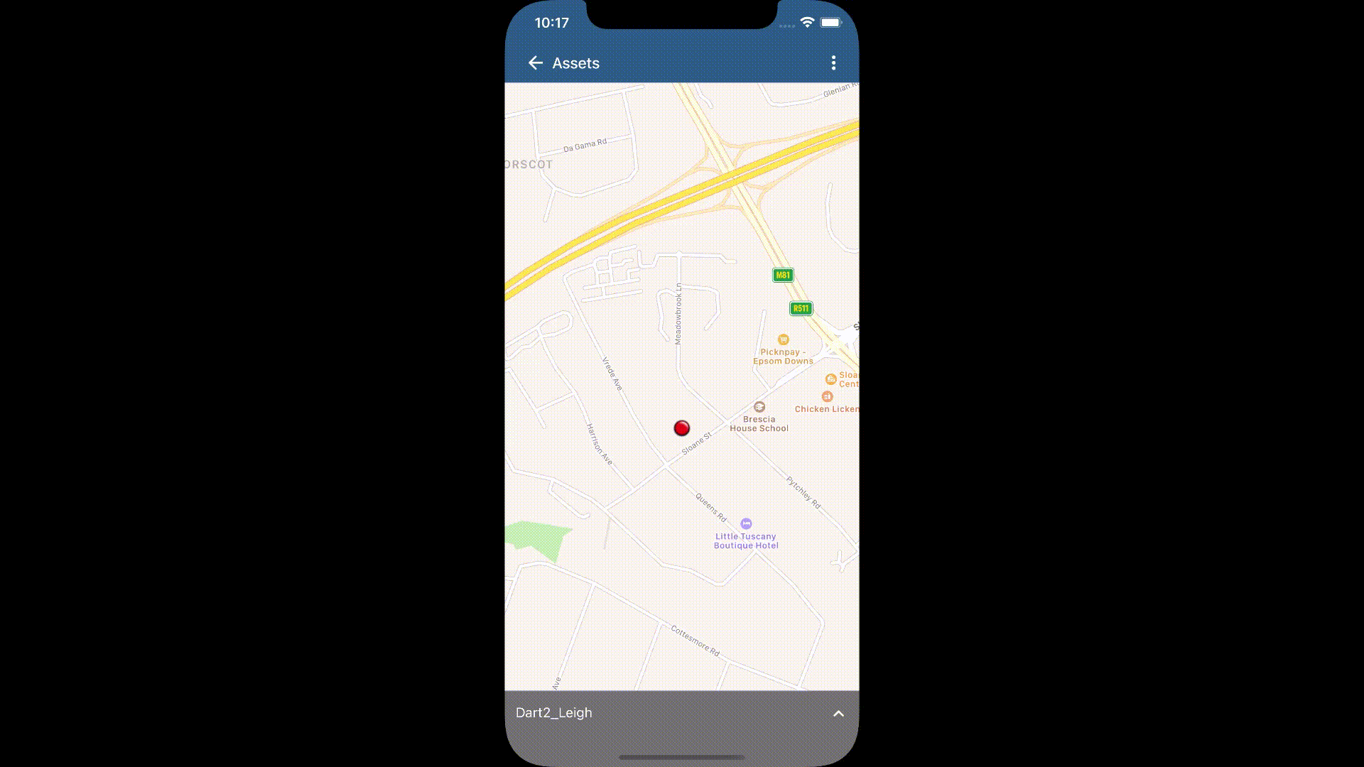
Or, from the app:
Check user permissions!
In order to see and use the 'immobilize' buttons on the app or website, your user account must have the Asset Manage permission. Remove this permission to take away a user's ability to immobilize an asset.
Sending an Immobilization message from a 3rd Party Server
A 3rd party server can also send a message to the device to immobilize.
- For those using Device Manager and a TCP or HTTP connector, the Device Manager Web API can be used to send this message
- For those taking the device data directly, the device can be messaged directly.
ASYNC Message Delivery - When will the immobiliser kick in?
Async messages are used to send messages from the server to the device. These are used to:
These messages can only be sent to the device when it is connected to the server. Connections are triggered by the device. Triggers for the device to upload include:
The times when it is not connected, the message will not be delivered until the next connection. This includes:
Notes
What if the device is removed?
If the device is tampered with, or ripped out, the relay will then default back to the "normal" position. When the asset is installed for immobilization via a command from the server, the wiring diagram as seen above in the article is for normally closed, so if removed, the asset would be able to start. So cutting a unit out would allow an asset to be started.
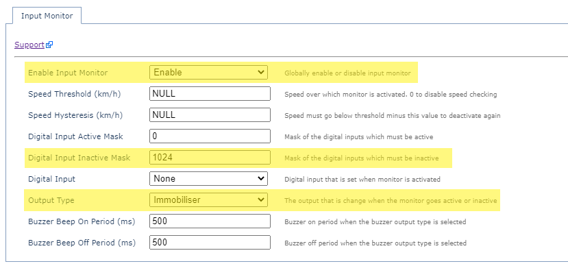
Configure Input Monitor
The input monitor allows immobilization to be set based on the state of device digital inputs, i.e. immobilize on external power disconnection. Below details how to set that use case up.
The external power tab will need to be set up to a specific digital input as seen below.
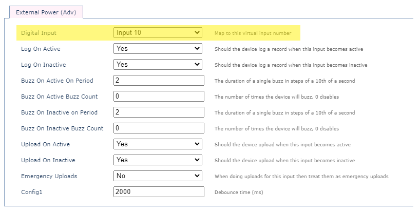
Once that has been added, the input monitoring tab can be enabled so that if the specified digital input is inactive the output type actions immobilization. The digital input inactive mask will need to be set to the digital input that external power is mapped to. For example, to have the input monitor action immobilization for when the above Digital Input (10) is inactive, this would result in a binary representation of the inputs as: 10000000000 which is the decimal equivalent of 1024.