Connect Hikvision Keypad

Written by Matthew Clark-Massera
Updated at May 23rd, 2024
Table of Contents
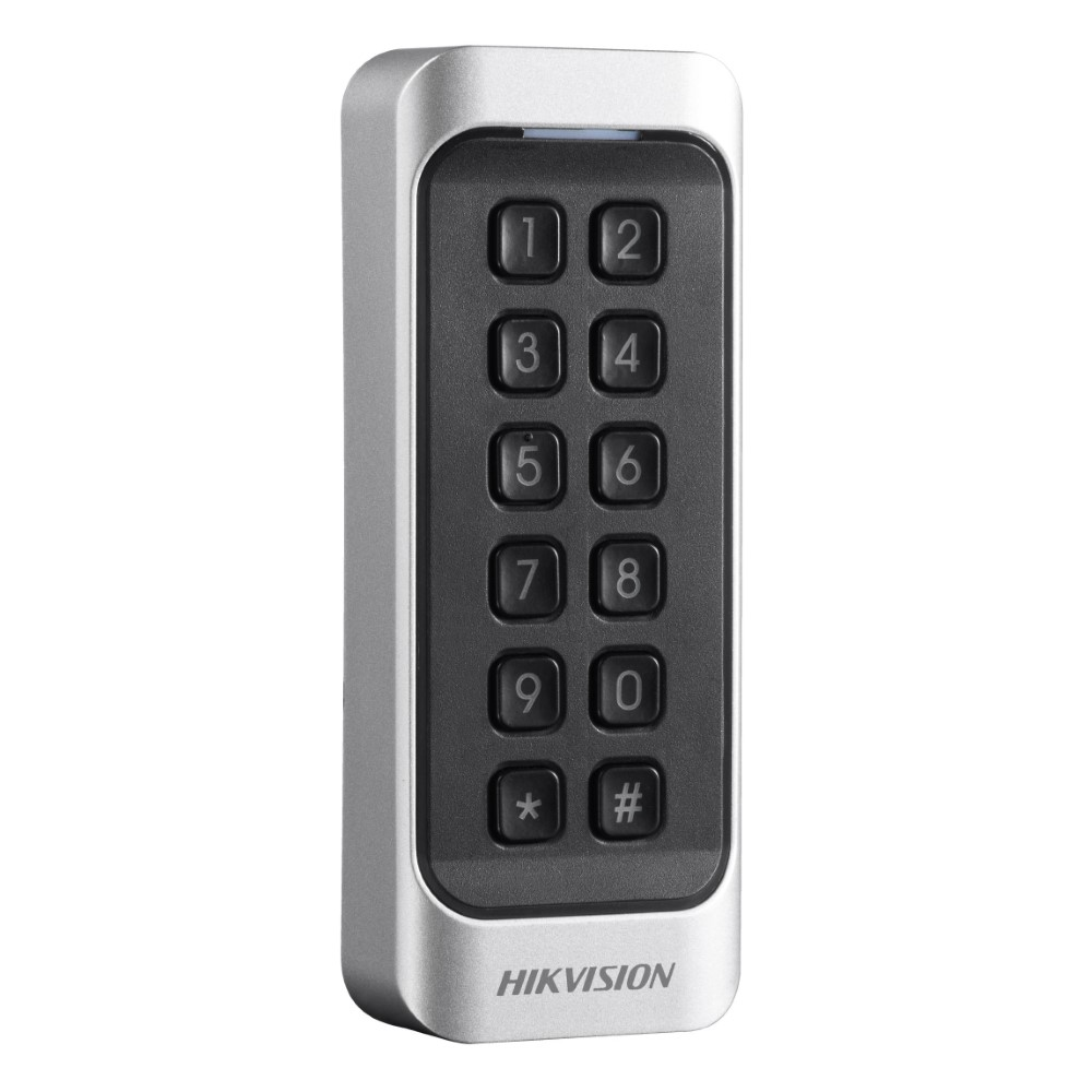
This article shows configuration steps to enable a Hikvision keypad to be read by the below list of devices. Consult the keypad manufacturer for detailed technical information.
Supported Devices
- Dart3 (2G and 4G)
- G70 (2G and 4G)
- G120 (2G and 4G)
- G150 Global
Product information
- Hikvision DSK1107 Web Page
- User Manual
- Australian Supplier - Security Wholesalers
Key functionality:
- IP65 keypad
- Good form factor - easily mounted with 2 x screws.
- Built in buzzer, which can be made to buzz in the same way as DM RFID readers with the correct wiring setup.
Warning - 12V Keypad
This keypad has an input voltage of 12V - ensure you do not exceed this!
This keypad sends each key press as soon as it is sent - but we have integrated it into the Dart3 firmware, so that when a certain parameter is enabled, the device stores each key press and only send through a completed code once the # key is pressed.
Note - there are 2 variants
| DS-K1107 - EK | This has both a Keypad for PIN input, and will read 125kHz EM4001 cards and fobs - which is the format used by our RFID readers |
| DS-K11078 - MK | Has a keypad and reads MiFare cards. |
Wiring
This a guide based on what DM have seen working, consult the manual for full details.
Dart3
Hikvision Keypad Wire |
Connect to |
| Red wire (PWR) | 12V DC power |
| Black (GND) | To ground - Pin 9 (Black) on 4 way driver ID connector on the Dart3 is easiest |
| Green (W0) | Dart3 Wiegand D0 Pin 4 - Green on 4 way driver ID connector |
| White (W1) | Dart3 Wiegand D1 Pin 10 - Brown on 4 way driver ID connector |
| Optional - Purple (Beep Control) | Dart3 Pin 3 - Purple - Switched Power Output |
G70
Hikvision Keypad Wire |
Connect to |
| Red wire (PWR) | 12V DC power |
| Black (GND) | Chassis or G70 GND |
| Green (W0) | G70 Wiegand D0 - Purple on 4 way driver ID connector |
| White (W1) | G70 Wiegand D1 Brown on 4 way driver ID connector |
G120
Hikvision Keypad Wire |
Connect to |
| Red wire (PWR) | 12V DC power |
| Black (GND) | To any ground - on G120, Pin 15 (Black) on 4 way driver ID connector is the easiest |
| Green (W0) | G120 Pin 14 - Green Wire on 4 way driver ID connector |
| White (W1) | G120 Pin 13 - Brown Wire on 4 way driver ID connector |
| Optional - Purple (Beep Control) | G120 Pin 9 - Orange Wire - Switched Power Output |
G150
Hikvision Keypad Wire |
Connect to |
| Red wire (PWR) | 12V DC power |
| Black (GND) | To any ground |
| Green (W0) | G150 Pin 7 on Harness 1 - Purple Wire |
| White (W1) | G150 Pin 6 on Harness 1 - Brown Wire |
| Optional - Purple (Beep Control) | G150 Pin 6 on Harness 2 - Brown Wire |
Parameter Setup
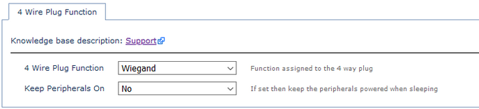
Ensure the 4 Wire Plug function is set to Wiegand
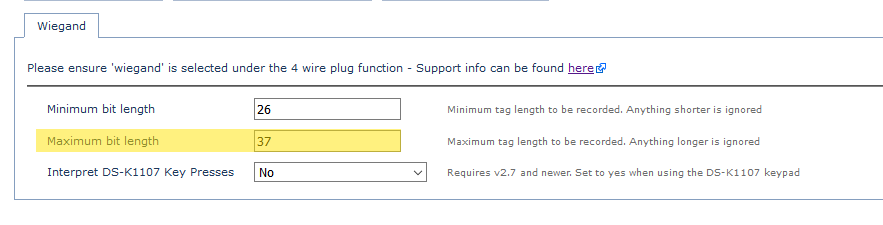
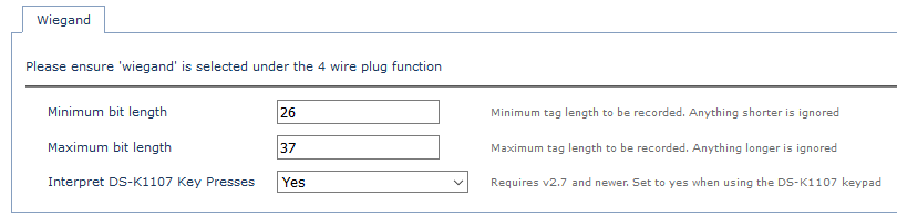
Ensure Interpret DS-K1107 Key Presses is set to Yes under the Wiegand Parameters
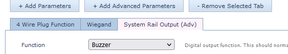
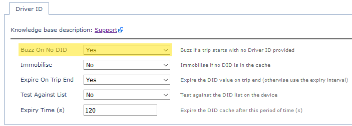
If we have wired up the buzzer control and want to enable buzzing, we need to set up this parameter:
Then, buzzing on no driver ID is set up as usual - see Immobiliser Install - Asset starts after valid Driver ID Scan for more information.
Operation and Usage
- The # key is "Enter" and * is clear. So to enter the code "1234" press 1234#
- If a few keys are pressed and are not followed by # - after 30 seconds whatever keys have been pressed will be sent as the code.
- The very first tag scan/entry after power on is ignored. This is not a problem in practice as the keypad should remain powered once installed as it requires 12V power, which would be supplied from a constant source.
- Number 6 on the DIP switches on the rear of the device must be on (this sets the keypad to output codes via the Wiegand interface) - the rest can be off.
- DIP switch 7 toggles between 34 and 26 bit Wiegand codes - default position (off) is 34 bit.
- Consult the manual for further information.
Driver ID Encoding
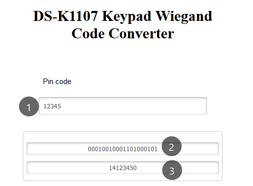
Wiegand IDs are typically made up of 2 bits to indicate the length of the data, 8 bits for a site code, then some data bits and finally a couple of check bits for error correction. So 12345# - i.e. entering the code 12345, is not sent by the device in this form. We can use the attached DS-K1107 input code -> end code converter.
An example:
To give out this ID for the DS-K1107 keypad.
- Driver Name: Peter
- ID - PIN code 12345
We would set up this keypad as per the instructions above.
Then we enter the code into the converter
|
1 - PIN code we wish to use 2 - Wiegand binary representation 3 - Hex representation for use in TG We then copy (3) into TG. This is what will be sent as the driver ID. |
 |
It is worth testing a few codes to ensure the values returned by the converter are correct.
We can use the Driver Code Field to provide a reference to what their PIN code is
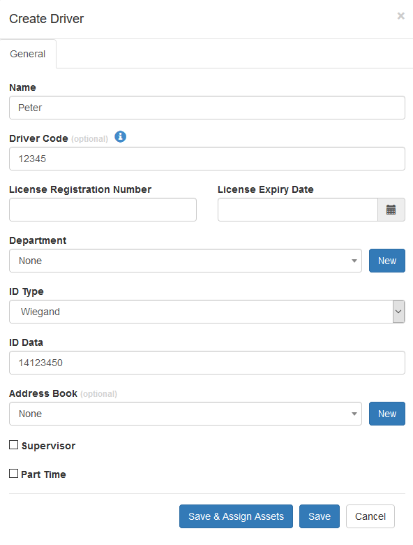
Then it will display in the driver list for easy reference.
The 10 digits available on the keypad mean a Licence number can be used as the PIN.


Then it will display in the driver list for easy reference.
The 10 digits available on the keypad mean a Licence number can be used as the PIN.

Testing and basic troubleshooting
To test for reads, it is best to keep the process simple. Various driver ID settings can mean that if a tag is not in the devices driver list - when it is scanned it is rejected on the device and not uploaded to the server. So it is hard to see if the reads work.
To test:
- Reset all parameters to default (remove the tabs)
- Only apply the 4 wire plug function = Wiegand parameter, and Interpret Key presses for simplicity
- Connect the reader
- Scan your tags - the reader should give some indication
- Tag scans don't cause an immediate upload - so to test it is good to put the device in trip by providing over 5V to the ignition line (this is how it will work in practice) - so scans will be immediately uploaded.
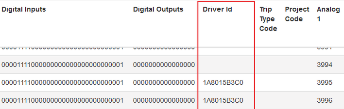
- Either Turn on Data Capture in OEM, or check the Driver ID column in Telemetry in Telematics Guru (Assets -> Telemetry) Successful reads will appear here.

If you don't get any reads here
- Try swapping the W0 and W1 connections in case they are mixed up
- Check all connections are OK, including power supply to the reader
- Try other cards - maybe the one you are testing isn't the format you think it is or is dead
- If all else fails, further debugging is difficult, contact DM and the end result be you will need to send us a card and reader to test.
- Increase the maximum bit length in parameters to 40.
- 37 is the default and is the longest we expect to receive. This provides some error correction, extremely long codes are probably errors and are ignored. However some readers may send longer codes - the maximum that can be read by the device is 40 bits.