Tenet Ultrasonic Fuel Sensor

Written by Matthew Clark-Massera
Updated at July 22nd, 2024
Table of Contents
Applies To
| Device | Firmware version |
| G120 | 2.12 and above |
| G150-Global | All Firmware versions |
The Tenet Ultrasonic Fuel Sensor supports integration with both the G120 and G150 devices via RS232. This allows for enhanced compatibility and flexibility in fuel monitoring setups. - the fuel level and temperature can be reported to the server in specified Analogues.
Additionally, readings can be made while out of trip and a drop in fuel level can be reported in a specified Digital Input.
Wiring
The sensor must be powered, and also connected to the RS232 port on the G120 and G150. Check the Tenet UL232 User Manual for more details.
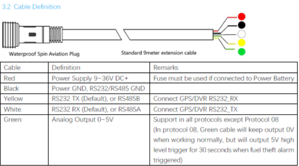
G120
Please refer to the G120 Harness definition.
- Sensor Red Wire -> Power supply (12V/24V)
- Sensor Black Wire -> Ground (any black wire on the G120)
- Sensor Yellow Wire (RS232 TX) -> G120 Violet, Pin 21 (RS232 RX)
- Sensor White Wire (RS232 RX) -> G120 Black/White, Pin 22 (RS232 TX)
G150-Global
Please refer to the G150 Harness definition.
- Sensor Red Wire -> Power supply (12V/24V)
- Sensor Black Wire -> Ground (Purple wire, Pin 7 on the G150 Harness 2)
- Sensor Yellow Wire (RS232 TX) -> RS232 RX (Blue wire, Pin 4 on Harness 2)
- Sensor White Wire (RS232 RX) -> RS232 TX (Pink wire, Pin 5 on Harness 2)
Installation
The device is to be fixed below the fuel tank (externally) using adhesives and straps. Consult the Tenet UL232 User Manual for guidance.
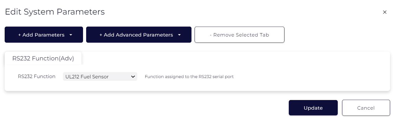
Parameter Setup
Add the RS232 function tab, and set the function to UL212 Fuel Sensor.
Typical Operation
Add the UL212 Fuel Sensor tab and Enable the sensor.
Typical operation involves reading fuel level and temperature data and reporting them to the server in the Analogues specified in (1) and (2) below. While in trip, the device will record the sensor value about once every 10 seconds.
While in trip, new logs are not generated for these reads, but as the devices generates other logs (i.e. the in trip 60 sec logs) – these values will be passed up to the server.
To log fuel level and temperature data while out of trip, specify a log interval in (3).
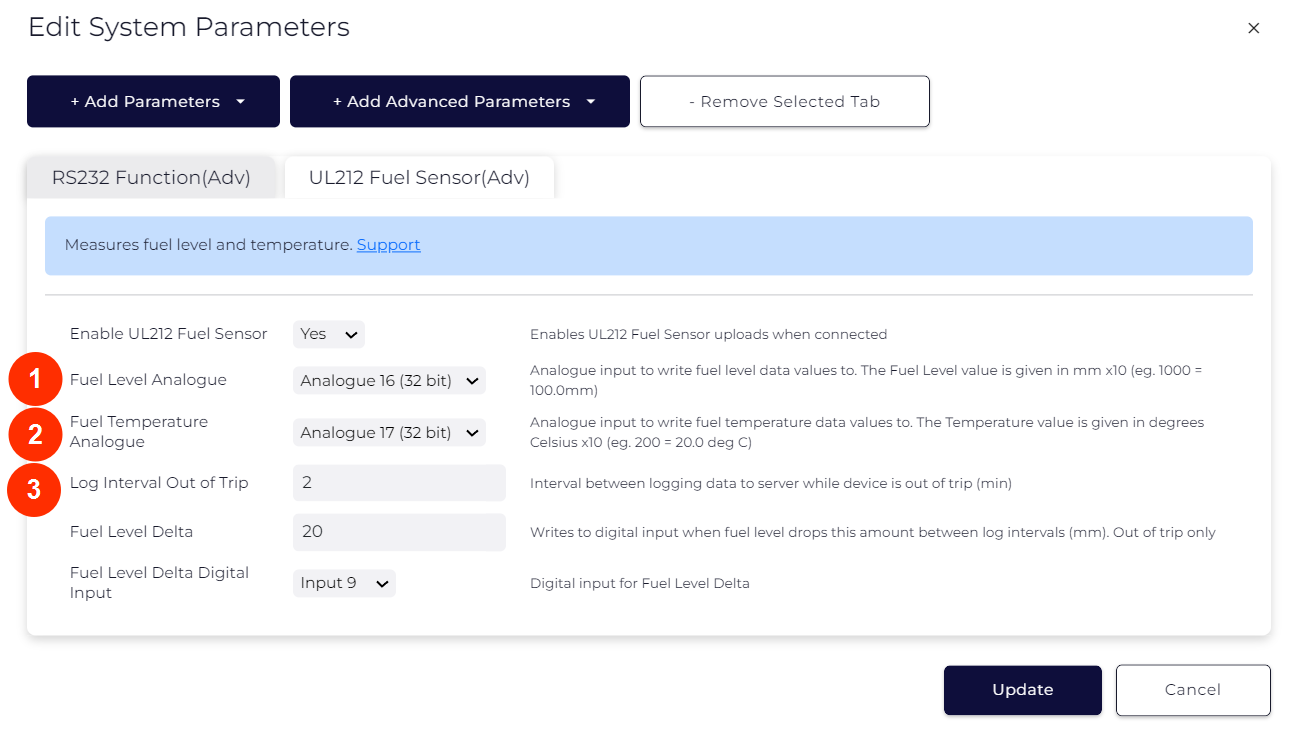
Fuel Theft Detection (Out of Trip only)
While out of trip, a drop in the fuel level between log intervals can be detected. Set an appropriate delta value in (4), this will depend on the size of your fuel tank, as well as the log interval out of trip (3) that was set. If the fuel level drops by the delta specified between two successive out of trip log intervals, the digital input specified in (5) will be set to 1 for this next log. An alert which is triggered by this digital input can then be set up on the end server.
Set up in Telematics Guru
Once we have configured the device parameters in OEM server, set up in Telematics Guru is simply a matter of creating an I/O mapping - i.e. to label Analogue 16 as 'Fuel Level'. Additionally, we also need to convert the raw value into a human-readable format.
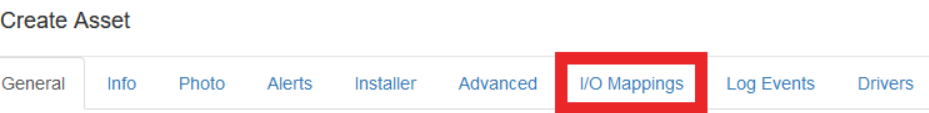
To set up, we just create an asset, and go to the I/O mappings tab.
Then we add analogue 16 (or whatever we have selected in our parameters to be the fuel level).
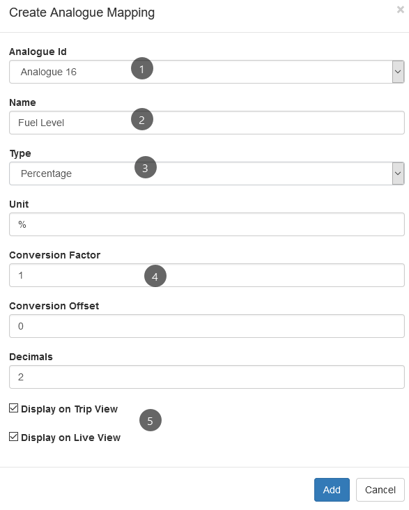
- Select the analogue where the level is being reported (16 in this case)
- Name the analogue
- We may elect to use "General" if we just want to report the value in mm - but percentage may be more useful to us. If we have multiple types of vehicle, with varying size tanks, this standardizes the measurement.
- We need to set up the conversion factor, more on that below
- Leaving these ticked ensures that the value appears on the live view popup.
Conversion Factor
The probe simply sends an ultrasonic beam to measure the distance from the bottom of the tank to the top of the fuel. So this gives us a 'level' - if we simply wanted to report this value in mm - we would set the conversion factor (4) to 0.1 - as the raw value is in mm x 10. How we can convert to a percentage is best explained by an example:
Conversion Example:
Our fuel tank is 1m deep (top to bottom) - the reading reported by the sensor is 5000 (raw) = 500mm. We know this means our tank is 50% full.
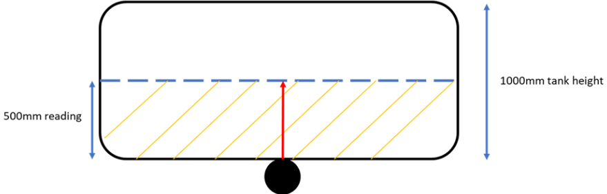
So our equation to get the percentage at any time would be:
Reading ÷ Full tank value * 100
i.e. for the above reading/10000 * 100. (10 000 because 1000mm is reported as 10 000 as a raw value)
So our conversion factor is 0.01
Troubleshooting
If you find the sensor is not working as expected, you can retrieve debug logs from the OEM server using INFO level debug data capture. See Turn on Debug Logging for more information.
To interpret any messages from the sensor as to how it is operating, please see the following table:
| Software Code | Description | Hardware Code | Description |
|---|---|---|---|
| 0 | Normal operation | 0 | Normal Operation |
| X | Probe powered and initialized. | 2 | Probe dropped, disconnected or detached. |
| H | Tilt angle too big or range more than 1 meter | ||
| 6 | Refueling Alarm | ||
| 9 | Fuel theft alarm |
The most common issue seen if the sensor is not operating properly comes with hardware code 2.
Possible reasons for this code include the following:
1. The probe does not have silicon grease applied when reading data.
2. The tilt angle is too large.
3. The probe does not have the correct position.
4. The probe is detached from the fuel tank or mineral water bottle.