G120 & G150 Iridium Set Up and Operation

Written by Matthew Clark-Massera
Updated at February 13th, 2024
Table of Contents
G120 or G150 Quick Start Guide
This article is intended as a complete guide to the available Iridium System parameters, and also to describe how the Iridium connection operates on the G120 or G150. For a cheat sheet to quickly get up and running, see the G120 & G150 Iridium Quick Start Guide.
Introduction
The G120 and G150 have the option of being connected to an Iridium Edge module. The Iridium Edge module contains an Iridium SBD modem and antenna, which allows the G120/G150 to send data when the cellular network is not available (e.g. out of mobile coverage areas). Because of the higher costs of Iridium SBD data, the G120/G150 firmware has been designed to allow it to be configured to only send a subset of the normal data based on the applied parameters. Upon returning to coverage the full data set (stored in device memory when out of coverage) is uploaded to the server.
Key Considerations/Caveats
- The G120/G150 + Iridium is not a device to be used permanently out of coverage. It is a 'hybrid' device designed to rely on the cellular network, but use Iridium as a stop-gap when out of coverage.
- Firmware and parameter updates can only be done in cellular coverage
- Telematics Guru only processes the Iridium records to handle alerts, and update the map. Iridium data is not used in reports, the trip history view etc. As soon as the device comes back into coverage and uploads its stored data these will be updated.
- The G120 & G150 talk to the Edge modem via the RS232 interface. So the RS232 port cannot be used for other purposes when we are using it for Iridium.
Iridium Set Up CheckList
(Steps 1 and 2 are the minimum requirement to have a device connected via Iridium.)
- Install Iridium Edge Modem and device according to the wiring diagram/install guide provided by Iridium.
- Enable Iridium Parameter set to Yes
- If any input changes are required to be transmitted via Iridium (e.g. duress buttons), the input mask must be set. (See more about Bit Masks below)
- Enter the decimal representation in the parameters - in this instance 12.
- Set out of GSM coverage timeout and in trip logging period if alternate parameters are desired.
Bit Masks.
To determine the bit mask:
If we require Digital Inputs 2 and 3 to be sent when they become active over Iridium), the binary representation of this is 1100 - bits 3, 2, 1, 0. So if you need Digital input 1 and Ignition, You add the decimal value together to get the Input mask value which is 2. Or if you need to upload if any of Digital Inputs 4, 5 or 6 are activated, the bit mask value is 8 + 16 + 32 = 56
Binary bits are counted from right to left, and the rightmost (least significant) bit is bit 0
Bit value (decimal) |
64 |
32 |
16 |
8 |
4 |
2 |
1 |
0 |
Digital Input name |
Digital Input 7 |
Digital Input 6 |
Digital Input 5 |
Digital Input 4 |
Digital Input 3 |
Digital Input 2 |
Digital Input 1 |
Ignition |
Switching To Iridium
For Iridium hardware requirements please refer to the following article
The G120/G150 will always attempt to send data on the cellular network as a priority.
If the GSM modem cannot REGISTER on the network within the Out of GSM Coverage Timeout (5 min default), then the assumption is made that the modem is out of GSM coverage the Iridium Modem will be used. As soon as the GSM Modem gets signal and is able to register on the network then the Iridium connection will no longer be used.
Default Behaviour
For a device on default parameters, when in coverage it will log and upload according to its regular parameters as below:
- Hourly Heartbeats
- Beginning and end of trip positions and uploads
- Logging on 60s time elapsed, 500m travelled, heading change, distance travelled, speed change, etc (there are many things the G120/G150 can be configured to record!)
Iridium Default Parameters
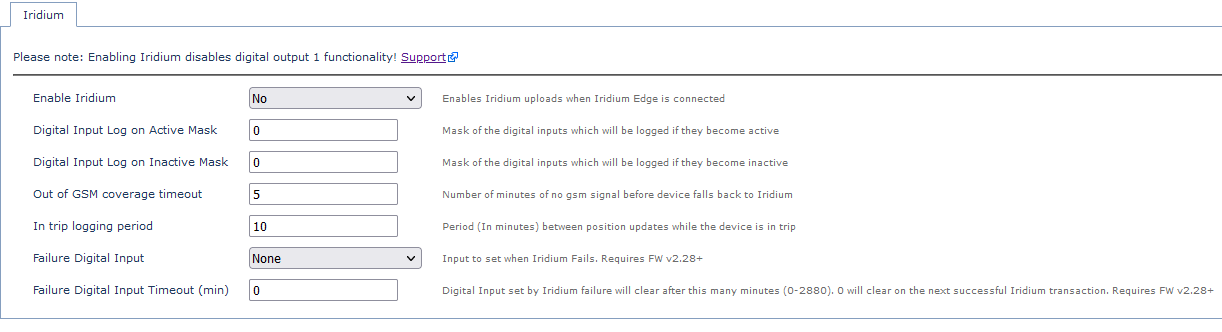
Enable Iridium
Enable or disable the iridium fail-over
Digital Input Active/Inactive Mask:
This is a bit mask controlling which digital input changes are logged. Active applies to the input going on. Inactive applies to the input going off. The number entered is the decimal conversion of the binary value for the bit mask.
0 = no digital input logging
1 = input 0 (ignition) is logged - there is no need to set this as the Ignition is logged anyway.
2 - in binary this is 10, so only input 1 is logged, useful for panic buttons!
3 - in binary 11, so input 0 and 1 are both logged
Out of GSM coverage timeout
How long, in minutes, before a failure to upload is considered a GSM failure and the device fails over to Iridium
In trip logging period
How often to log an Iridium record when in a trip
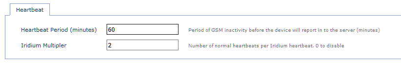
Heartbeat period
How many times a normal heartbeat should happen before an Iridium heartbeat record is logged.
For example, if the normal heartbeat is 1 hour, setting this to 5 would result in an Iridium heartbeat every 5 hours.
Iridium Logging
The following records will be uploaded when the G120/G150 is using Iridium.
Trip Start/End
This will always be logged and sent when on Iridium
Digital Inputs
Optional logging and uploads of Digital Inputs 0 to 7, if configured in the parameter masks. Allowing for important inputs to be sent e.g. panic buttons.
Period In Trip
A position update is sent every In Trip Logging Period (default 10 mins as per Iridium parameter tab shown above)
Accident/Rollover
Accident log reasons will always be logged and uploaded, giving an immediate notification of this.
Heartbeat
When out of trip, it will heartbeat according to it's Iridium heartbeat parameter - which is specified as a multiple of the GSM heartbeat. 2 hours by default.
Note
The device will still log (but not upload) all the same records that it would while in GSM coverage and store these in memory. This means the complete, 30-second, turn-by-turn trip record data will be sent to the server upon returning to GSM coverage.
Iridium Session Failure Flag
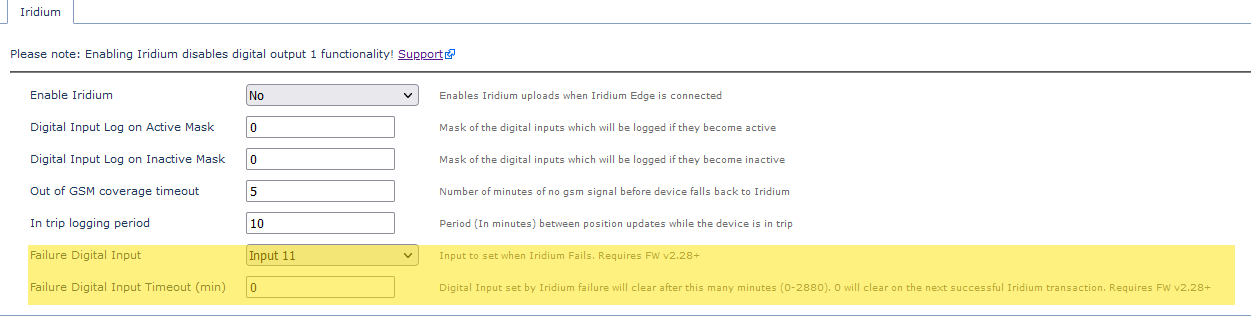
A Failure Digital Input can be configured to aid in troubleshooting - Iridium Troubleshooting.
If an Iridium session fails, the following input will be set. It will be cleared on the next successful session, or after the failure timeout.
This can help with detecting faults. If a device leaves coverage, and cannot upload over Iridium, upon returning to coverage, we will be notified that a message failed to get through. This may allow the unit to be looked at prior to leaving coverage again (maybe it is back where it can be worked on)
In Telematics Guru - set up an alert on the digital input selected.
Records Sent over Iridium
Given we only have a 20-byte record (see Record Size below) to work with, only a subset of the complete data is sent with each Iridium upload. The message will contain,
- The log reason (why the record was generated) - e.g. Heartbeat, Trip Start, Elapsed Time
- Trip Status bit - to say if it is currently in or out of trip
- Sequence Number + Date Time
- GPS position - Lat and Long
- Current speed
- Current Heading
- Digital Inputs 0-7
In order to estimate your required usage you will need to estimate how long the G120/G150 will be operating with no GSM coverage and what your parameters are set to.
Calculating Iridium Data
Digital Matter offers Iridium Data bundles for devices using the Telematics Guru platform.
The package you need depends on your requirements, and the amount of time the asset will spend out of coverage.
3KB
this for light compliance, where tracking outside mobile coverage is essential for safety etc, approx 150 messages per month, for vehicles that “may” go out of coverage
8KB
This plan is the normal, approx 400 messages per month, for vehicles that go out in and of coverage regularly but not for particularly long periods
15KB
This plan is approx 750 messages, for vehicles that go out of coverage often but are generally based in mobile coverage
30KB
Approx 1500 messages, for vehicles that go out of coverage a lot and stay out (exploration, remote camps, construction and civils equipment).
You can also use the attached spreadsheet to estimate the amount of monthly uploads you will get over Iridium based upon time spent out of coverage and device settings.
This will help with choosing your plan and adjusting your settings to stay within the upload limit, to avoid overage charges.