Driver Fatigue Monitoring

Written by Matthew Clark-Massera
Updated at August 8th, 2025
Table of Contents
| Device | Firmware Version |
| Arrow Global Bluetooth® | All Versions |
| Dart3-2G, Dart3-4G, Dart3-4G Bluetooth®, Dart3 Global Bluetooth® | All Versions |
| G120-2G and G120-4G | All Versions |
| G150-Global | All Versions |
| G70-2G, G70-4G, G70-4G Bluetooth® | All Versions |
Hard-wired devices have the capability to buzz and/or set a digital output after a period of time in trip.
Overview
- When a trip starts, the warning and alert countdowns begin.
- These countdowns will continue until they elapse, the trip ends or idling is detected (optional)
- When the warning countdown elapses, the warning buzzer will sound, and when the alert countdown elapses the alert buzzer will sound and any enabled digital outputs will be set.
Use-Case
Typically, this is used for driver fatigue.
- The warning buzzer is used to alert the driver that they are nearing their maximum allowable driving time
- The alert buzzer is used to alert the driver that they have reached the maximum allowable time and must take a break as soon as possible.
- Digital outputs can be utilized, wired to a light or a buzzer to provide in-cab feedback to drivers these periods have elapsed.
Resetting the timer/countdown
The countdown is based on trips, and begins when a trip starts.
It ends either when the trip ends, or idling is detected (configurable). The assumption being, if idling is detected, the driver has stopped for a break but left the ignition running while parked.
Driver Fatigue Parameters
Parameters for the Arrow Global BLE, Dart3 and G70 are as follows

Behaviour shown in the example above:
- Once a trip starts, fatigue timer begins
- Warning period - After 105 min (1hr 45)
- A connected buzzer will sound 5 times are sounded - 1 second each buzz (1s buzz, 1s silence x 5)
- Alert Period - After 135 min (2hrs 15 min)
- 10 x buzzes are sounded - 1 second each buzz (1s beep, 1s silence x 10)
The maximum Warning/Alert Period is 1275 minutes (21 ¼ hrs)
The G120 and G150 have 2 minor differences:
- Fatigue Warning Period

- The Fatigue Warning Period maximum is 255
- The units are minutes, or minutes x5 (providing the same absolute maximum of 1275 min (255 * 5)
- Enable Digital Output 1 + 2

- As there are 2 x Digital Outputs available on the G120/G150 either (or both) can be configured to be enabled when the Alert timer is reached.
Reset Fatigue Timers when Idle
When set to No, the timer will only reset when the currently in progress trip ends. If we have a hard-wired ignition line - a trip remains in progress while this line is active.
So if a driver drives for 2hrs, then parks up for 15 minutes, with the ignition running (many do so the air-con can run while they rest), this will not register as a break and reset the timer.
Example:
- Drivers must not drive for more than 2hrs 15 min continuously
- They must take a 15-minute break at this time. (We want sitting stopped, but idling to count)
We would configure as in the above screenshot, but set Reset Fatigue Timers when Idle to YES
Then we must configure Idle Monitoring - Idle Monitoring

Configuring Buzzers
Expand below to view information on connecting a buzzer to sound after reaching Warning or Alert Periods
Connecting Buzzers
Connect an External Buzzer/LED
The Arrow Global BLE*, Dart3, G70 and G150 can be set to sound buzzers based on various conditions such as:
- A trip starting, but no driver ID has been scanned - to remind drivers to tag on. This is configured on the Driver ID parameter tab, see Immobiliser Install - Asset starts after valid Driver ID Scan
- Digital Inputs being active/inactive. This is configured on the Digital Input parameter tab, see Digital Inputs
- Harsh driving events. Configured on the Harsh Driving parameter tab, see Harsh Event Setup
- Speeding events. The buzzer will sound when going over a certain speed. Configudigitalmatter.helpjuice.com/en_US/%20immobiliser-install-asset-starts-after-valid-driver-id-scanred on the Speeding tab, see Speed Monitoring
- When speeding inside a geo-fence - Geofence Downloads Example: Buzz when over 40km/h inside geofence
*Noting the Arrow Global BLE provides only 1 x Switched Ground Digital Output, some of these features may require 2 x Digital Outputs to implement, i.e. Immobiliser and buzzer.
To have a buzzer sound, we need to do 2 things:
- Correctly wire the buzzer, and configure the right parameters to tell the device we have a buzzer connected
- Configure one of the options above to set under what conditions we want buzzing to occur.
What we will cover below is how to set up the output to behave correctly to make a buzzer beep (i.e. beep, beep, beep). This is achieved by having the device toggle an output on/off. If we connected an LED instead of a buzzer - the LED would flash. So this concept can be extended to anything we might want to behave in a pulsing on/off manner.
Buzzer Options
- The DM RFID reader also has an internal buzzer - no set up required - just plug and play for ultimate ease of install.
- The G150 (and the older G120) has an internal buzzer, located on the PCB (it may not always be loud enough if installed under the dash)
- We can configure digital outputs on devices to sound an external buzzer which we wire in.
When we set the device to 'buzz' i.e. buzz on no driver ID - all options we have set up will buzz. If we had an RFID reader also connected that device's buzzer will sound at the same time. We don't need to do any special configuration for (1), so we will discuss (2).

Example - Piezo Buzzer from Multicomp.
Installation and Setup
Switched Ground as a Low Side Switch (preferred option)
The Arrow Global BLE, Dart3, G70 and G120 have switched ground outputs. See: Digital Outputs for more detail. Switched Ground outputs can be thought of as a low side switch. They are high impedance (open circuit, no connection) when off, and provide a path to ground (i.e. close the loop) when on.
Arrow Global BLE
The Arrow Global BLE has a Switched Ground output
Digital Output 1 - Wire 6 - Yellow
G70
The G70 has a Switched Ground output
Digital Output 1 - Pin 8 - Green
G120
The G120 has 2x Switched Ground outputs
- Digital Output 1 - Pin 11 - Yellow
- Digital Output 2 - Pin 10 - Green
Wiring
- Connect the high side of the buzzer to a constant power source - that is within the buzzers input voltage range. This could simply be to the vehicle battery, or to an ignition source (but then the buzzer is only provided with power when the ignition is on)
- The low side of the buzzer to the switched ground output on the device. This is the Yellow Wire or Green wire.

In this configuration, the buzzer is constantly powered, but the switched ground output going on/off has the effect of connecting and disconnecting the negative terminal to ground.
When the negative terminal is connected to ground (SW GND output on) there is a complete circuit, and the buzzer sounds.
Parameters
Digital output
Add the Digital Output 1 tab and set the function to “Buzzer”
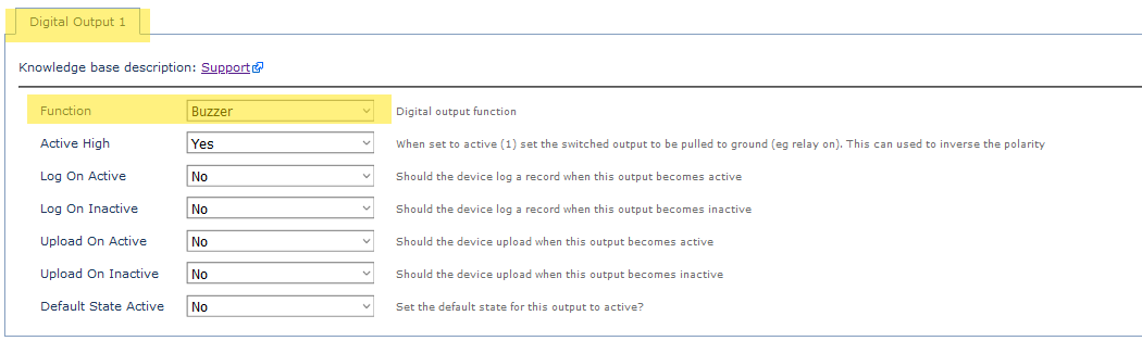
So now, if an event occurs that means the device will buzz (like over speed, or harsh braking) - the output line will pulse on, off, on, off, on, off... - to sound the buzzer.
System Rail Output on High Side of Buzzer - Dart3
This option is generally less preferable, as it means we must source a buzzer that is within the 3.5-5V, 500mA range (rating of output). However if we are already using the Switched Ground for another use (i.e. immobiliser) - it may be required.
Pin 3 (Purple) is normally used to provide power to a DM RFID reader. Instead, we can cut the 4-way molex connector and connect it to the high side of a buzzer.
Wiring

- Connect the High Side of the buzzer to the Dart3 Purple Wire
- Connect the low side to Ground - Chassis ground or any of the black wires on the Dart3 harness can be used.
Parameters
Set the System Rail Output function to Buzzer
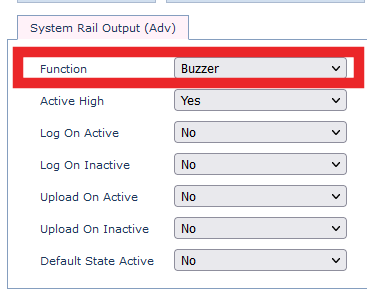
Now, when the device decides to 'Buzz' - the purple wire will pulse on and off.
Switched Power Output - G120
The G120 also has a Switched Power Output (Pin 9 - Orange). These are not used as commonly but may have some useful applications and can be utilised when the switched ground is otherwise being used.
Instead of providing a ground when on, and disconnected when off - these outputs provide a voltage source when on. The G120 will provide 5V at the pin when the switched ground output is on. In this case, we wire the negative terminal of the buzzer to ground, and the positive side to the Switched Output wire.
Parameter setup is essentially the same, just we use the Switched Power Output tab to control the behaviour of this output.

Fatigue Monitoring in 3rd Party Platforms
Aside from the in-cab feedback, generally exception alerts and reports are required server-side - to inform supervisors of any times drivers have missed fatigue breaks.
The Fatigue Warning and Fatigue Alert Digital inputs can be used.

If configured the end server needs to only look for these inputs becoming active to flag a Fatigue Event.
Alternatively, reports can be run based on total trip time.
Fatigue Monitoring in Telematics Guru
Alerting on Fatigue Events
When the Fatigue Alert is active and threshold is met, the device will log a 'digital input changed' log reason - since devices are connected to the server constantly during a trip, it will connect and upload to TG.
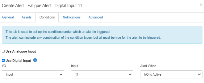
- Go to Alerts ⇾ New Alert (Advanced)
- Set up the alert as required: general, asset, notifications, advanced.
- In the conditions tab, specify “Use Digital Input”:
- Choose the digital input you have set in the driver fatigue tab within OEM.
- Choose alert when I/O is Active
Running Reports
We can create an Event, and then map this alert to an event to be able to report on instances of driving without breaks.