High-G Event Detection
Table of Contents
Supported Devices
Barra Family
| Device | Firmware Version | Notes |
|---|---|---|
| Barra GPS | All | - |
| Barra Core | All | - |
| Barra Edge | All | - |
| Barra Recovery | All | - |
Oyster Family
| Device | Firmware Version | Notes |
|---|---|---|
| Oyster3 2G + Oyster3 4G | All | - |
| Oyster3 2G + Oyster3 4G | All | Oyster3-4G Digital Input Mapping available in v1.17/v2.17+ |
| Oyster3 Global | All | - |
| Oyster3 Bluetooth 4G | All | Multi-Axes High-G available in 1.4+ |
| Oyster Edge | All | High-G logging up to 16G available in 1.20+ |
| Oyster1 3G | 1.6+ | - |
Yabby Family
| Device | Firmware Version | Notes |
|---|---|---|
| Yabby3 | All | - |
| Yabby Edge | 1.12+ | - |
| Yabby GPS and WiFi | All | - |
Remora Family
| Device | Firmware Version | Notes |
|---|---|---|
| Remora 2 4G | All | Multi-Axes High-G available in 2.21+ |
| Remora 3 4G | All | Multi-Axes High-G available in 1.5+ |
| Remora3 Global | All | - |
| Remora1 3G | 1.35+ | - |
Manta Family
| Device | Firmware Version | Notes |
|---|---|---|
| Manta Fusion | All | Multi-Axes High-G |
| Manta GPS CATNMB | All | Multi-Axes High-G |
| Manta Fusion Global | All | Multi-Axes High-G |
High-G event detection is supported by our battery powered device range.
When enabled, the device accelerometer will detect High-G events exceeding the specified force and duration and log a record containing:
- Log Reason 46 - 'High-G Event'
- Record Time
- Last known GPS time and position (FID 0)
- The Peak Force (FID 24)
- The Average force (FID 24)
- The Duration of the High-G event (FID 24)
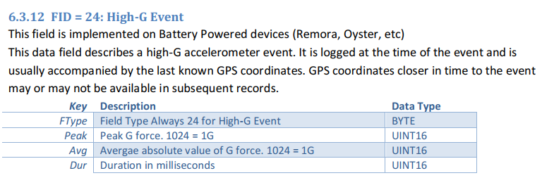
Snip from device playload specification below

The Peak, Average and Duration is the resultant force across 3 axes.
For the devices which support Multi-Axis High-G, 9 values are returned (vs 3)
The order is these appear in the device payload is
- Peak X
- Peak Y
- Peak Z
- Average X
- Average Y
- Average Z
- Peak Overall
- Average Overall
- Duration Overall
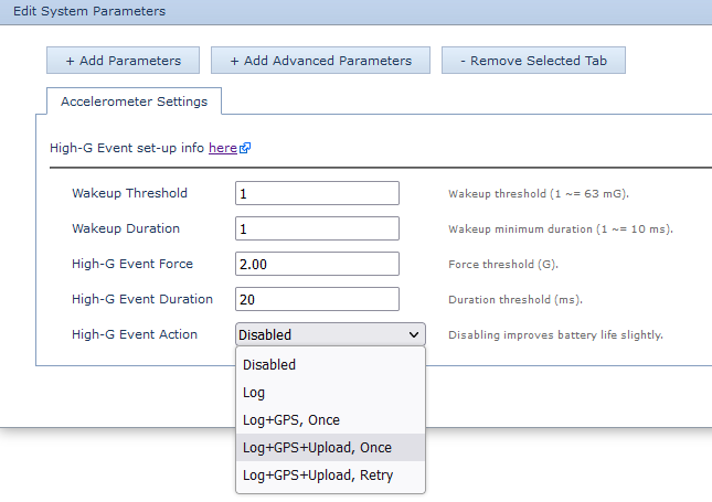
Since the immediate record contains only the last known GPS position, the High-G Event Action can be configured to attempt a GPS fix after each High-G event to pinpoint the location.
It can also be configured to attempt an upload with the result of the fix once, or to continue retrying the fix/upload until the device succeeds, with increasing back-off timeouts in the event of failure.
Enabling High-G Impact Detection
Current Range
Barra Edge, Barra Core, Barra GPS, Oyster3, Oyster3-BLE, Oyster Edge, Remora3, Yabby3 and Yabby Edge
- Add the accelerometer settings parameter tab, and select High-G as the alternate function

- Add the High-G detection parameter tab, and configure the High-G thresholds and Action

Multi-Axis
For devices which support Multi-Axis logging, simply set the High-G Axes Logging dropdown to Yes to log in 3 axes

Older Products
Eagle, Falcon, Oyster v1, Oyster2, Remora v1, Remora2, Yabby GPS, Yabby WiFi

- Edit System Parameters and add the Accelerometer Settings Tab
- The High G Event force, Duration and Action can be configured
Selecting the High-G Threshold
Because the accelerometer is sensitive to gravity, it wakes up more easily when experiencing vertical forces. However, gravity is not considered when evaluating the criteria for logging. This filters out nuisance events from speed bumps, but might in extreme circumstances allow many High-G event wake-ups to go unnoticed, as they did not lead to a logged event.
When using High-G detection in situations prone to repetitive vertical forces (for instance, on corrugated roads, or with continually vibrating machinery) be sure to set the force threshold high enough to avoid repetitive wake-ups, and the associated battery use.
The default threshold of 2Gs is suitable for regular vehicle tracking, where continuous vertical forces are not expected. To determine the minimum safe threshold in challenging environments:
- Set the High-G Event Force threshold to its minimum value (1.5 G @ 10 ms)
- Test the device in its intended application
- If the detector doesn't go off, a threshold of at least 2.6 G is safe
- If it does go off repeatedly, add at least 1.1 G to the reported peak force
High-G Event Detection Battery Life Implications
Because High-G detection requires the accelerometer to run at a higher speed than usual (100 Hz, versus the usual 12.5 Hz), it is disabled by default. This saves a small amount of battery.
The table below outlines the battery consumption from running the accelerometer at a higher speed when High-G events are enabled.
High-G events may also trigger extra fixes and uploads, so this will also increase the battery consumption. Therefore you should factor this in when estimating the battery life.
| State |
Current (uA) |
% AA Lithium Battery/ Year |
| Accelerometer Off |
0 uA | 0% |
| Accelerometer Low Power | 1.64 uA | 0.45% |
| Accelerometer High Power | 2.5 uA | 0.68% |
| High-G Low Power | 7.2 uA | 1.97% |
| High-G High Power | 14.9 uA | 4.08% |
In addition to requiring additional battery power for the accelerometer, High-G events use battery when responding to each event. The device must wake up whenever it sees a large force, and verify that the force meets the criteria for logging.
Configuration Examples
Oyster3: High-G events for portable toilet tips
The Oyster3 supports High-G and Tip Detection. While both features are set off based on accelerometer activity exceeding certain thresholds, for some applications Tip Detection cannot be used. This is because that Tip Detection works only in one particular axis. High-G Impact Detection can be used for such applications where we are interested in something falling over - which will result in a crash and some G-forces seen.
In this article, we will covers the parameter setup to monitor assets that can easily tip/fall-over in 2 axis. We will consider the example of a portable toilet.
Parameters
Below is how the Oyster3 operates out of the box
Default Tracking Parameters - [Oyster3]
- In Trip (on the move):
- Upload on trip start.
- GPS points every 2 minutes
- Upload every 30 minutes
- End a trip after 5 minutes of no movement (or losing GPS)
- Upload on trip end.
- Out of Trip (stationary) - heartbeat every 12 hours. This is a GPS point and uploads every 12 hours.
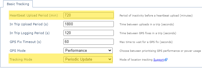
For a stationary asset like the portable toilet, infrequently moving it may not be necessary to track trips. Getting the location update once or twice a day should be sufficient. It will maximise battery life and minimise data usage. Periodic Tracking will let you do this.
To set the Oyster3 to periodic tracking, set the "Tracking Mode" to Periodic Update and "Heartbeat Period" to 12 or 24hr update.

High-G detection is disabled on the device by default. This can be enabled from the Accelerometer Settings parameter tab. Set the Alternate Function to High-G.

Once selected, the thresholds can be added from the High-G Detection parameter.

Mounting
Though there are no special requirements as to how the device should be mounted for High-G detection, it is recommended that the device be mounted high up on the asset. This way, the device should see a clear high-G event on falling over and experience decent G force. This means we can set the threshold a bit higher and better filter out false alerts.
Testing
There is not a particular threshold that we suggest for any application. The specific force threshold will be dependant on the size of the asset and the nature of the fall. So some initial testing/trial and error may be required.
We want to set the threshold such that an event is reported when the toilet falls over, and not if it is transported between locations.
To aid in this, while testing we can leave the device in its default tracking mode (GPS Movement Trips). This can make it easier to identify the correct thresholds.
In this way, if the device goes in trip when there is GPS movement, and if you get any High-G events during the trip, then we can increase the thresholds based on this. - as we know the level of G force experienced in-trip.
Once we identify suitable threshold we can then set the device to Periodic Tracking.
Configuring High-G Events Video:
Setting Up Alerts and Event Reports
Alerts in 3rd Party Platforms
When a High-G event is detected, the device will log a record as per listed above.
- Log Reason 46 - 'High-G Event'
- Record Time
- Last known GPS time and position (FID 0)
- The Peak Force (FID 24)
- The Average force (FID 24)
- The Duration of the High-G event (FID 24)
- Digital Input set to indicate event*
*currently available only for the Oyster3-4G
As such alerts can be set up to fire when Log Reason 46 is seen or specific Digital Input set (Oyster3 only).
*Oyster3-4G allows the option to set the parameter for a Digital Input to be set when an event occurs. This might be useful as some systems have already integrated alerts for Digital Inputs 0-10 for example, or we can map it to an input our other devices use.
If you do not integrate the High-G data FID 24, you will not receive peak, avg, duration. Inputting alone on the input field is enough to alert an event occurred based on the above configured threshold.

Alerts and Reports in Telematics Guru
Analog Mappings
In Telematics Guru, the High-G event data reported by the device in Field 24, is transposed to Analogs 12-20, as per below, which should be configured on any devices utilising High-G event detection.
12-17 are only reported for devices with Multi-Axes reporting enabled.

Configuring Alerts
See how to set up an alert here.
Ensure to give the alert a name and message in the General Tab; apply the alert to the relevant assets in the Assets Tab, and select who TG should send the alert to under Notifications.
In the Conditions tab, select 'Use Device Data Log Reason' and select High-G Event from the list that's populated.

High-G Event Reports
The below 3 reports are available in Telematics Guru.

If they are not visible within your organisation, you may need to edit the organsation and add them, or contact support to have them added.
