Yabby Cellular Default IO Mappings
The Digital and Analogue mappings for the Yabby are explained below. Please note the minor differences between Telematics Guru mappings and what is received in the raw data. Telematics Guru manipulates the raw data.
Telematics Guru
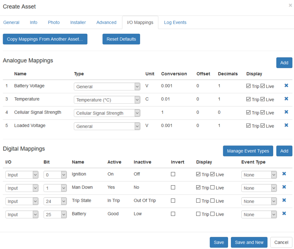
On Telematics Guru, the defaults are shown graphically below.
For the Analogue Mappings, the analogue number is on the left. The meaning for that number is given in the name. The type, unit and conversion factor explain how to interpret the number. The conversion factor can be thought of as the multiplier to convert the raw number to the right unit.
For the Digital Mappings, the digital input/output number is on the left. Note inputs vs outputs. All Yabby default mappings are inputs. The digital input/output bit explains the position in the Digital Data bit field.

DI 0, Ignition, will be on when the device is moving, and off when it is not. The device maps this to Emulated Ignition - it allows for the concept of a Trip in TG
Not Shown:
The Battery Status is also mapped to DI 2 - however it is unecessary to also map it to TG, as it is available as DI 25 in TG already, (bit 1 of the status flags for raw data)
Raw Data from OEM
The raw data will appear slightly differently to what is show above in Telematics Guru. Here are the key differences:
- Analogues 1-10 come in the 16 bit analogue field ID.
- Analogues 11-20 come in the 32 bit analogue field ID.
- Digital Inputs come in the Digital Data field, as 4 bytes. This is a total of 32 inputs. The status bits shown above (Trip State; Battery) are not in these 32 bits.
- Digital Outputs come in the Digital Data field as 2 bytes. This is a total of 16 outputs.
- The Status bits come in the Digital Data field, as 2 bytes. This is a total of 16 bit flags:
- Trip State is bit 0 of the status bits
- Battery Good is bit 1 of the status bits.
