Measuring 4-20mA Current Loop Signals with an Analog Input

Written by Matthew Clark-Massera
Updated at January 27th, 2023
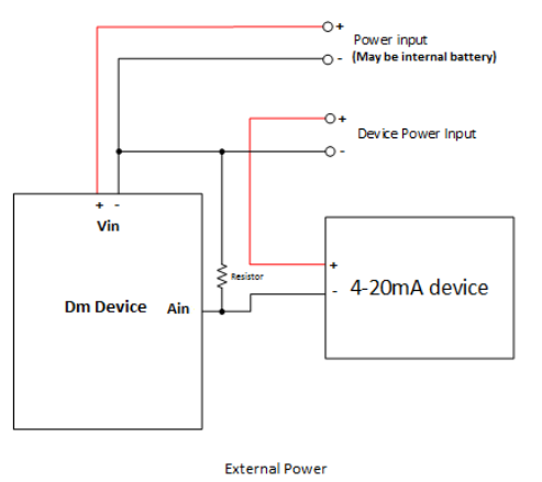
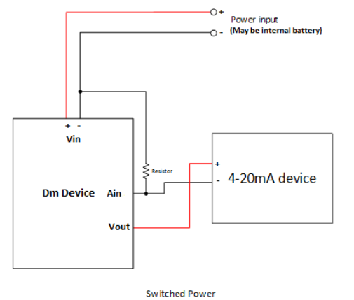
To measure a 4-20mA current signal, a resistor should be wired inline to the low side of the power to the device (possibly supplied by the device itself), and analog in be wired to the high side of the resistor (see diagram). Selection of the value of resistance is a trade off between measurement precision, and the input voltage range of the device being powered (as well as the input range of the device).
Most of our devices have (automatic) dual ranges of 0-5V and 0-30V. It is preferred to use the 0-5V range, so to get the most precision, the resistance required would be 5V / 20mA = 250 ohms. The downside of this is that when the device is outputting 20mA (some devices may also output a slightly higher current to signal a fault), there will be a 5V drop across it's input voltage. So if the device was powered from 12V, it would now see 12 - 5V = 7V at its input. This may be outside of its operating range. To remedy this, either the input voltage may be increased (pay attention to the maximum input voltage ratings of the sensor), or the resistance can be decreased.
For the above example, running from 12V, and a device that runs from 9 - 12V, we can calculate the resistance by (12 - 9) / 20mA = 150 ohm. This would create a voltage drop of 3V at 20mA, and allow the device to be fully powered. The downside of this is that only 3/5 = 60% of the input range is being used (which may still be fine for most applications).
When receiving the values on the server, they will be in mV, and need to be converted back in to mA. To do this simply use the following formula V / R = I, where V equals the received voltage (in mV), R is the chosen resistor value, and I is the final current value (in mA).
To conclude:
- Note the maximum and minimum input voltages on the telemetry device and device being powered.
- Calculate the maximum allowable voltage drop across the resistor (Vin minus Vdrop must be greater than Vminimum(device)).
- If applicable, adjust input voltage to allow for a higher voltage drop (must be lower than the maximum input voltage).
- Calculate resistance from voltage drop - V / 0.02 = R.
 |
 |