Eagle - Wiring up a DM Temperature Sensor

Written by Matthew Clark-Massera
Updated at February 2nd, 2023
Table of Contents
This guide is to be read in conjunction with the DM Temperature Sensor Datasheet.
Digital Matter manufacture and supply a Temperature/Humidity (Ambient) I2C Sensor, and an I2C Temperature Probe. Check the above data sheet for specifications.
 |
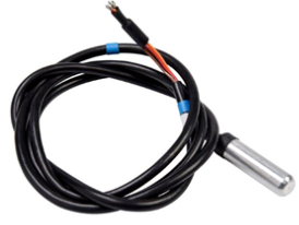 |
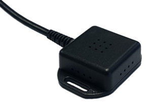
| Ambient Sensor (Temperature and Humidity Sensor) | I2C Temperature Probe |
Connecting the Sensors
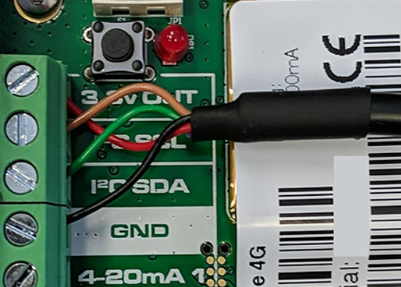
Please note, Wires will need to be inserted through the gland in the housing first, then wired into the PCB.
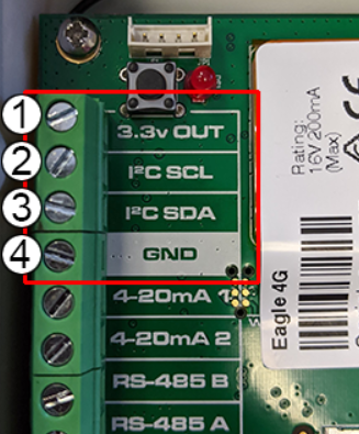
On the board, you will see a strip of screw terminals, 4 of them are used for the I2C Bus.
- 3.3V Out
- Sensor Clock
- Sensor Data
- Grounded
The connections for each sensor are as follows:
DM Ambient SensorWiring Table
Note: The wires are inserted into the front hole next to the label. unscrew the clamp section of the screw by rotating counter-clockwise, then insert wire.
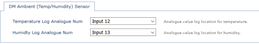
When configuring system parameters for the Falcon (or other DM devices), to read from this sensor, ensure readings for "Ambient Sensor" are enabled.
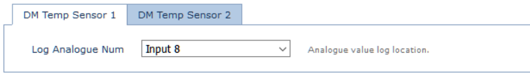
DM Temperature ProbeWiring TableEach I2C sensor has an address. For the Ambient sensor this is set at the factory and fixed to one address. Connections are as follows:
Where the green wire is connected dictates which sensor you should select when setting up your system parameters. E.g it is connected to GND, set the Falcon up to measure "DM Temp Probe 1"
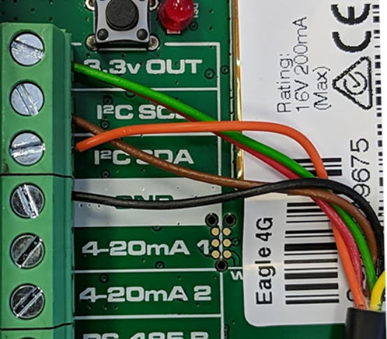
An image of the connection for DM Temp Probe 2 is shown below with the green address wire connecting with 3.3V Out, for probe 1, move the green wire to the ground terminal.
|
Viewing Sensor data in Telematics Guru
Please view the knowledge base article on configuring and viewing sensor data in Telematics guru platform