Dart3 Wiring and Installation guide

Written by Fezile Mojapelo
Updated at January 19th, 2026
Table of Contents
The Dart3 is supplied with a 12-wire harness. The harness contains pins for various I/Os. For many installs, where we simply are looking for 'standard' vehicle tracking, we only need to connect 3-wires.
For quick plug-and-play installs, there are additional Dart3 harness options (OBDII harness, Cig Lighter harness) - or the Bolt2 is a good option. The benefit of a 3-wire 'hard-wired' install is that the device can't be easily dislodged/removed, and - a ‘true’ ignition signal can be detected. Meaning trip starts are recorded with pinpoint accuracy - and idling can be effectively monitored.
Tools and Items Needed
Before beginning installation, ensure you have the following:
- Fuse Tap Connectors – for tapping into vehicle wiring
- Pliers – for gripping and bending wires
- Multi-meter – to verify voltage and ground connections
- Wire Strippers/Cutters – for preparing wire ends
- Screwdrivers – for opening panels or securing mounts
- Zip Ties or Fasteners – to secure wiring and device
- SIM Card – for cellular connectivity
- Protective Gloves – for safety during installation
Harness Pin-out and Wiring
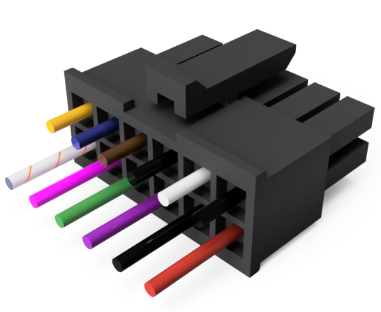
- The Dart3 comes with a 12 wire, 650mm long harness
- 15mm is pre-stripped on the input (red), ground (black), and the ignition (white) wires.
- Wire gauge is 0.35mm²
Harness diagram
 |
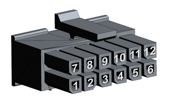 |
| Pin | Wire Colour | Function |
|---|---|---|
| 1 | +VIN / Battery (8–33V) | |
| 2 | Ground | |
| 3* | VOUT (Power Output) | |
| 4* | Driver ID 2 / TTL RX / Wiegand D0 / Digital Input 3 | |
| 5 | Digital Input 1 (Max 48V) | |
| 6 | Analog Input (0–30V) | |
| 7 | Ground | |
| 8 | Ignition Input (0–48V, active >2.2V) | |
| 9* | Ground | |
| 10* | Driver ID 1 / TTL TX / Wiegand Data 1 / iButton | |
| 11 | Digital Input 2 (Max 48V) | |
| 12 | Switched Ground |
Pins marked with an asterisk (*) are routed to the 4-way Molex connector for RFID reader integration.
Basic 3-Wire Installation
For standard vehicle tracking:
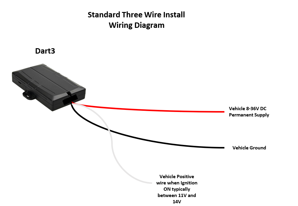
- Use a multi-meter to locate a fuse that supplies power even when the vehicle is turned off (such as the hazard lights or interior/door lights)
- Connect Red (Pin 1) on the Dart3 harness to this or the vehicle battery (8-33V).
- Connect Black (Pin 2 - or any black wire on the harness) to chassis ground
- Use a multi-meter to locate a fuse that will only supply power when the vehicle is on - such as indicator lights.
- Connect White (Pin 8) - to this point.
- The White ignition input will register as 'on' when >2.2V is applied to this line.
NB: It is best to avoid ‘tapping into’ a safety critical system such as the ABS.
Fuse taps such as the below may be used for a clean install.

Mounting Guidelines
- Mount the device securely using zip ties or brackets.
- Place the device with as clear a view of the sky as possible, in order to maximize GPS signal.
- Avoid mounting near metal surfaces or electronic interference sources (e.g., radios, ECUs).
- Route wires neatly and secure them to avoid vibration damage.
Additional Install Options:
Connect Digital Inputs:
- Door Open
- 4WD Active
- Seat belt monitoring
- Panic Buttons
See Digital Inputs Introduction - the device parameters must be configured first for this to correctly function.
Connect Analog Input:
Pin 6 (Orange) is for voltage-based sensors e.g. fuel float switch.
Driver ID:
A plug and play Driver ID reader is available (supplied by DM) - incorporating an RFID reader and internal buzzer.
Alternatively, iButton or Wiegand readers can be used.
See:
When wired in tandem with an automative relay, the asset can be configured to be immobilised until a valid ID is presented and/or a command is sent from the server.
- Immobiliser Install - Asset starts after valid Driver ID Scan
- Immobilisation Install - Asset can be immobilised from server
Pins 4 and 10 for RFID/iButton. Driver ID 1 and Driver ID 2 are used for various functions depending on configuration. Either:
- Driver ID 1 and 2 can be used to connect a Digital Matter RFID reader (plugs in via the 4 way Molex connector)
- Driver ID 1 can be used as the iButton Data Line, and Driver ID 2 can be used as a 3rd Digital Input. This can be independently or simultaneously.
- Driver ID 1 and 2 can be used to connect Wiegand Driver ID readers
Switched Ground:
Pin 12 for controlled grounding to drive external buzzers, or immobilise the asset.
See:
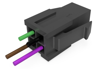
Molex Connector
The four way Molex connector comes as part of the 12 way harness, with pins 3, 4, 9 and 10 from the main harness going to the connector. This can then be used for a plug and play connection to the DM RFID reader.
 |
 |
| PIN | COLOUR | FUNCTION |
| PIN 1 | GROUND | |
| PIN 2 |
|
TTL RX / Wiegand D0 / Digital Input 3 |
| PIN 3 | VOUT | |
PIN 4 |
Tnd DTL TX, Wiegand 1, iButton |
Molex Connector Details:
Some partners may choose to build their own harnesses or fit a suitable mating part to the 4-way molex connector to their own Driver ID readers to simplify installations.
To assist with this, part numbers of the connectors on the Dart3 wiring harness are shown below.
| 12 way Main Connector | Connector Housing Receptable 12 position 3mm straight bag | Part Number: 43025-1200 |
| 4 way Molex connector | Micro fit 3.0 plug housing, dual row with panel mount ears, halogen-free, 4 Circuits | Part Number: 43020-0400 Mouser Link |
Plug and Play Connection Options:
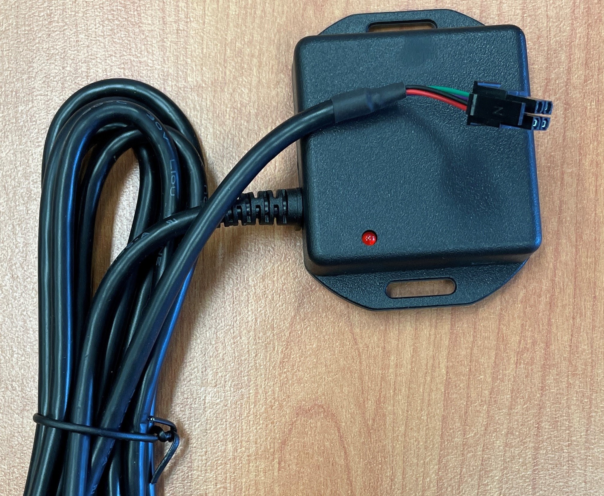
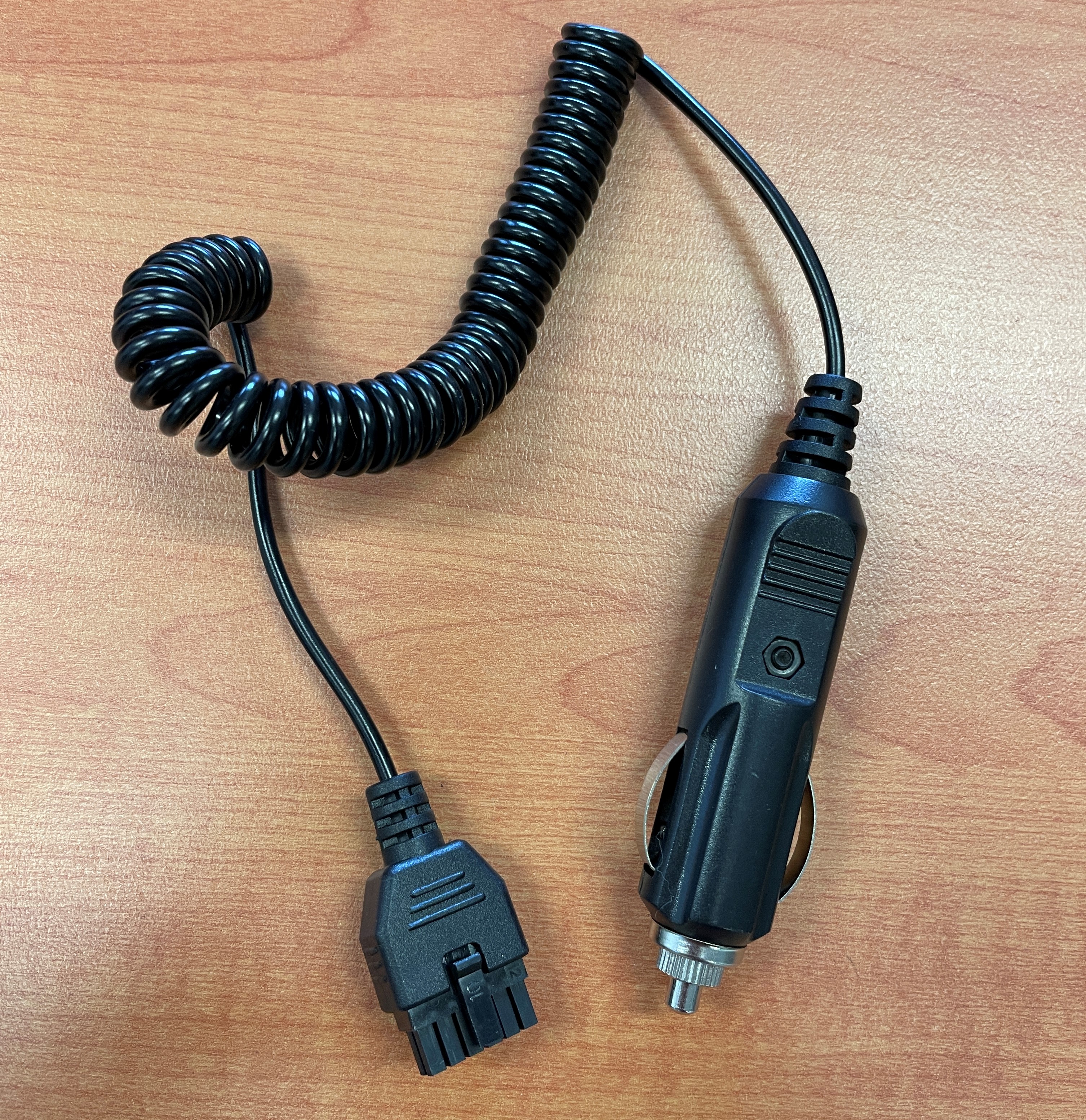
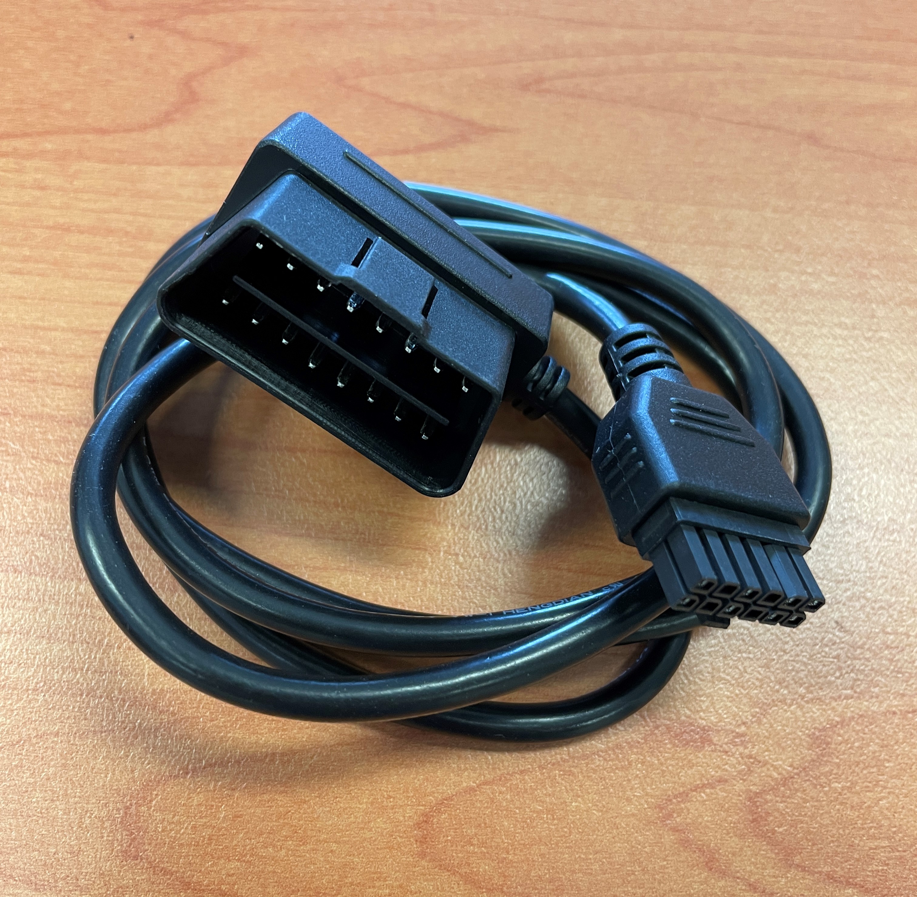
We also have an OBD harness or a Cigarette Lighter harness options available for a quick install, or alternatively - consider the Bolt2
Please note that you will not be able to get an ignition trip if you are using either of these harnesses, since a dedicated ignition wire is only available in the 12-wire harness. The device will work out trips based on movement or change in voltage.
 |
 |