Configure Buzzing on Excessive Tilt - G70

Written by Matthew Clark-Massera
Updated at February 3rd, 2023
Table of Contents
Most Digital Matter devices are fitted with a 3D accelerometer. Our hard-wired range of devices make use of the accelerometer for harsh event detection, accident detection, and monitoring activity, trips and idling.
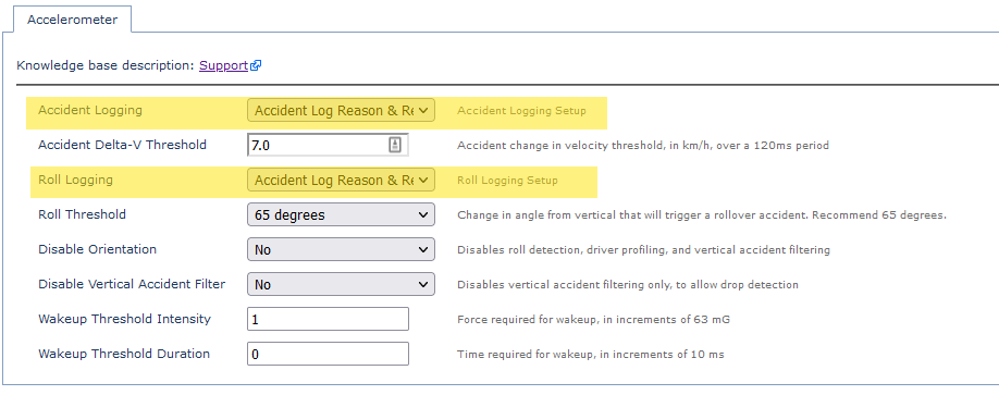
Accident Detection functionality allows for a Roll Threshold to be set. Once this is exceeded an accident is logged and uploaded to the server so action can be taken.
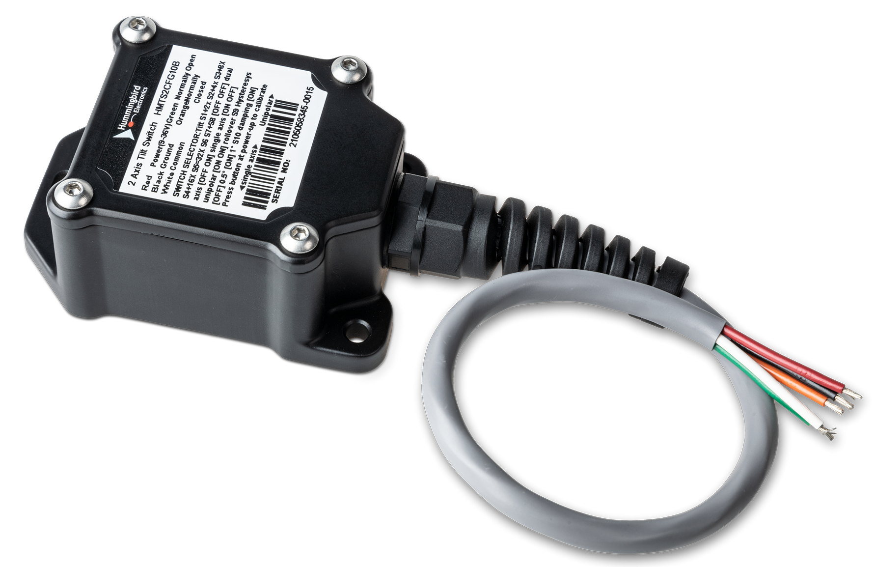
For certain applications though, we want to provide in-cab feedback to the driver and log an event - vs triggering a full rollover accident alert. Consider a mower fitted with a G70 in this example. We need to get an in-cab feedback when the mower is operating tilted at an angle which is over the accepted range. We are using a Hummingbird 2 AXIS TILT SWITCH and a buzzer for this application.
Humingbird 2 Axis Tilt Switch
Setup
Wiring
Please see G70 Harness Definition. The G70 has three Digital Inputs.
To set up either Digital Input 1 or 2 you will need to use the corresponding wires.
- Digital Input 1 = BLUE
- Digital Input 2 = ORANGE
- Digital Input 3* = PURPLE
*Digital Input 3 is shared with one of the Driver ID lines, so DI3 cannot be used at the same time as a DM RFID reader, or Wiegand Reader.
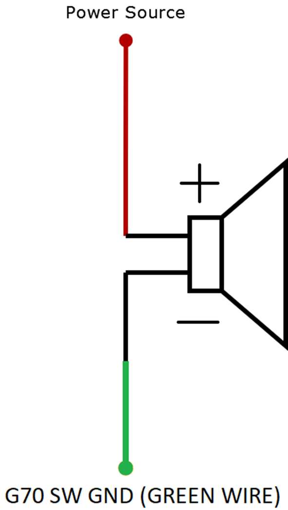
To ensure that the buzzer is only powered when the mower is on (ignition is ON), we connect the high side of the buzzer to the ignition source. This means the buzzer can only sound when the mower is in use.
Connect the low side of the buzzer to the Switched Ground, Pin 8 - Green Wire in the G70 harness.
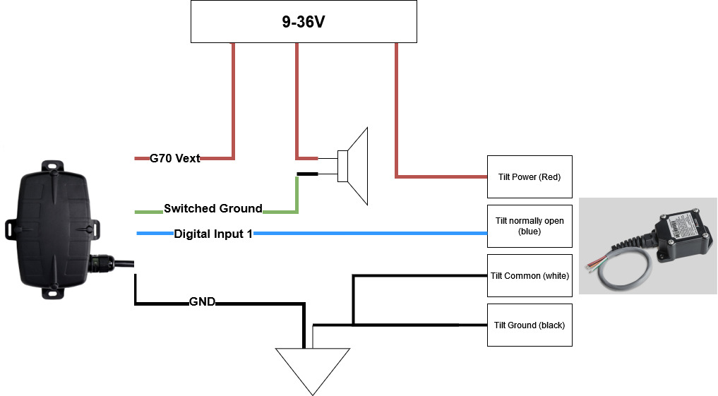
Connect the Tilt Switch to either DI1 or DI2 of the G70 harness.
The Hummingbird Tilt switch operates at 9-36V voltage range. The harness definition is as below
- White Wire = Relay Common
- Blue Wire = Relay Normally Open
- Brown Wire = Relay Normally Closed
Note
The wire colours are referred from the Hummingbird Tilt Switch user manual at the time of writing this article. Please visit the Hummingbird website for product manual and other installation information.
Connection Diagram
Parameters
Digital Input Setup
In the above configuration, the tilt switch is connected to the Digital Input 1 (blue wire) in the G70. So we add the DI 1 tab and set up the below
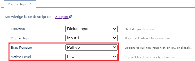
- Bias Resistor set to Pull-Up
- Active Level - Low
In this setup, when the device is operating within the accepted tilt angle, the input is held high, i.e, the buzzer will not sound. When the device goes over the the accepted operating angle, it then completes the circuit with the relay normally open-blue wire of the tilt switch, so now the buzzer will sound.
Buzzer Parameter
The below parameter from the Digital Input tab needs to be configured for the buzzer to function when the digital input is active.

The Buzz on Active Buzz Count parameter determines how many times the buzzer sounds when the input is active. This can be any number, but ideally you would want the buzzer to sound as long as the mower is operating over the accepted tilt angle. Setting the count to 255 will enable continuous buzzing as long as the digital input is active.
Telematics Guru Setup
Though this is not a mandatory setup to get in-cab feedback using the buzzer, setting up the I/O mappings on TG will enable you to configure alerts when the event happens, signal duress etc.
1. Create an Event Type
From Admin> Event Types, create a an event type with a meaningful name.
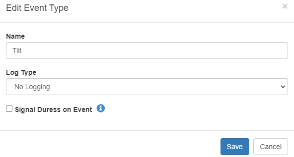
Checking the Signal Duress on Event checkbox will cause the Live View In Telematics Guru to play a sound as an event occurs.
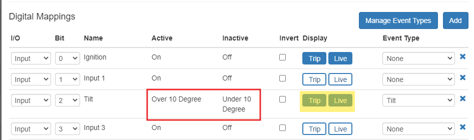
2. Edit the I/O Mappings
We have connected the Tilt Sensor to the Digital Input 2 on the harness. From the Manage Assets tab, Edit Asset by clicking on the asset name or from the cog menu on the right hand side > I/O Mappings> Add, and create the digital mapping.
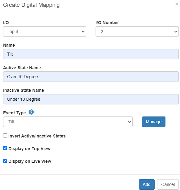
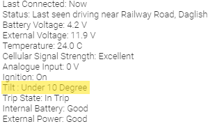
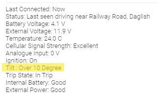
The Active State/ Inactive state name is whet will be be displayed on the Live View. The status of the device will be shown in the live view and Trip History view if you check the Trip and Live option in the I/O Mappings tab
 |
 |
Set up Alerts
From Admin > Alerts >New Alert Advanced, set up the alert as below
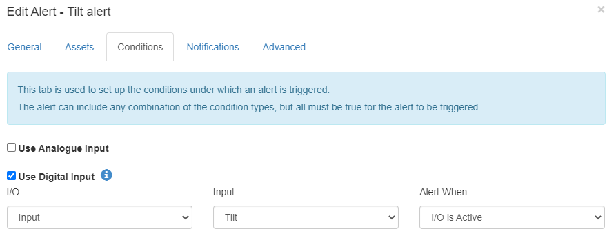
So now when the DI2 is active, an alert notification will be sent to any assigned user in the address book, and also the buzz will give an in-cab feedback.