Connecting a SensorNode Bluetooth® to an Eagle, G120, G150 or Remora2
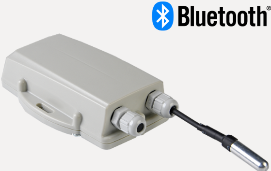
This guide covers how to configure the Eagle, G120, G150 or Remora2 so that it can read input data transmitted by the SensorNode Bluetooth.
digitalmatter.com
Getting Set Up
Articles to review
- Getting Started - SensorNode Bluetooth (covers wiring sensors)
- Updating Device firmware
- Updating Bluetooth Firmware
Set up BLE Scanning.
First off, we must set up the device to scan for BLE tags.
Please see this article for further detail and instructions on configuring BLE Scans
Multiple connection methods
There are 2 separate ways to connect the SensorNode BLE to a gateway device. Telematics Guru users should use one, and 3rd Party Platform users the other.
TG Method - Mapping SensorNode BLE Temp Readings to Gateway Device (Remora2, G120, G150, Eagle) analogues
This supports a maximum of 2 x SensorNodes per gateway device. We set it up such that the gateway will recognise the SensorNode's payload, read the data, and write the values of any Digital Matter Temp or Temp/Hum sensors connected to device analogues. This has the following benefits:
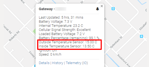
- Alerts/reports etc are easily configured within TG, just alert on the Gateway Device's analogue. We can display the temp on the live map also against the gateway device. Details on this are below.
- As far as TG is concerned, the SensorNode doesn't exist - the temp readings is just data against the gateway device. So there are no additional TG-TAG fees.
And disadvantages:
- A max of 2 tags per gateway
- Only DM temp probes or temp/hum sensors can be mapped to the analogues - the SensorNode also reports the status of it's other inputs (2 x Digital + 2 x Analogues) - and we can't see these in TG.
However this remains the method which should be employed with TG to get temp data.
3rd Party Platform Method - SensorNode BLE as a Tag:
While the first method can easily also be set up for those with 3rd party platforms (and is quite simple and convenient) -it comes with the 2 disadvantages which we can avoid via this second method. We treat the SensorNodes as a tag. The max limit of tags the device can store in its tag list is 512, much better than 2! Additionally we can also read the status of all device inputs. So this is the most flexible and preferred method for integrating tags into 3rd party platforms.
Set Up: 3rd Party Platform Method - SensorNode BLE as a Tag
When setting up tag scanning, select "DM SensorNode" as a tag type to be scanned for.
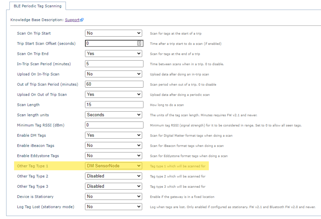
Then, the SensorNode BLE will just be recognised as any other tag would by the gateway device. It's data will appear in Fields 29 and 30. Tag type 5, with the following information:
- Tag Serial Number
- TX Power
- Battery Voltage
- Internal Temp (microcontroller temp, not highly accurate)
- DM Temp Probe 1 and 2 Temperature reading.
- Temp/Humidity Sensor Readings
- Digital Input 1 + 2 State
- Analogue Input 1 + 2 Value
So with this method, we can support any number of tags, and get all the inputs in our 3rd party platform.
Set Up: TG Method - Map Sensor Readings to Gateway Analogues
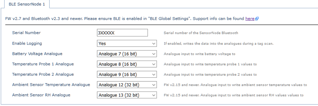
For this method, we simply configure scanning, then we add the BLE SensorNode 1 and BLE SensorNode 2 Tab. You can pair two SensorNodes to each Device with tab 1 and tab 2.
Up to 2 DM Temperature Probes and 1 x DM Ambient Temperature/Humidty sensor can be connected to each SensorNode Bluetooth.
To configure, we simply add a parameter tab, enter the serial, and select Enable Logging = Yes. Then, the rest of the parameters set which Gateway device analogue the values will appear in. Make sure you aren't clashing with any others already in use (particularly on a device like the Eagle where you might have many sensors hooked up)
Mapping SensorNode Digital Inputs to Gateway Digital Inputs
This option is currently available on:
- G120 FW 2.12 and above.
- Remora2 FW 2.18/3.18 and above
- All G150 FW
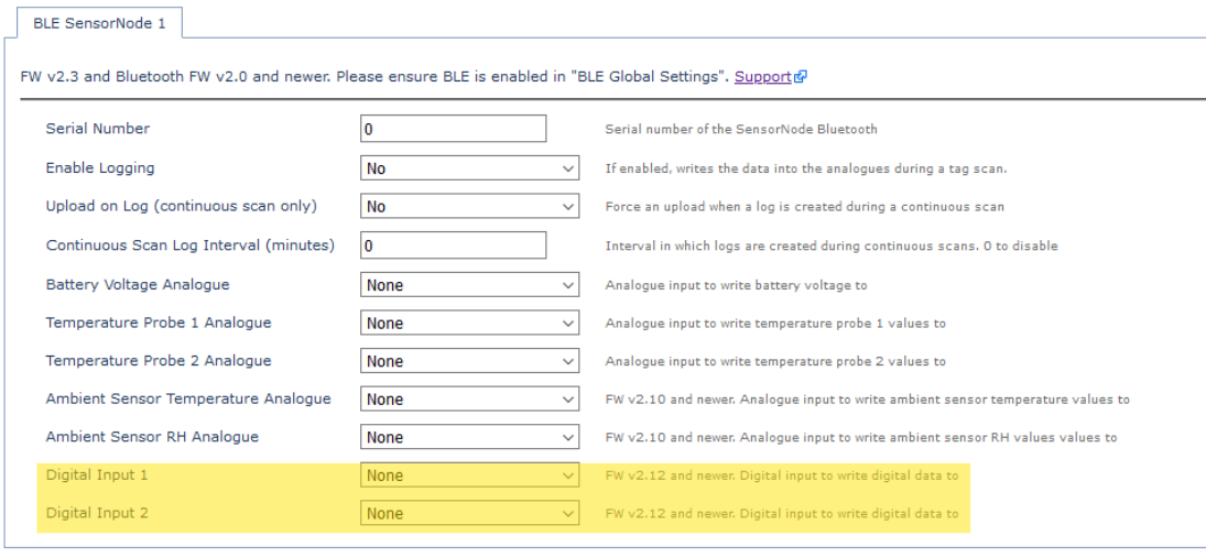
The SensorNode has 2 x Digital Inputs - bias resistor = pull down, active level = high. This means it will operate in the same way as an ignition input on a wired device - it will be active (1) when there is over 2.4V at the input, and inactive (0) when there is below 2.0V.
The state is broadcast every beacon. So these parameters allow the states to simply be mapped to the gateway's Digital Inputs - take care to avoid clashes in your setup.
This feature effectively allows for 'wireless' digital input monitoring - i.e. monitor the status of a pump or engine which is some distance away from the gateway. However there are some considerations/caveats that need to be taken into account:
- The potential for the tag to become 'lost' - i.e. go out of range needs to be considered - as then any alerts won't go off if configured and there is a state change
- If the SensorNode goes out of range, the Digital Input will be set to 0 on the gateway. Alert setup needs to cater for this.
Displaying Temperature Data in Telematics Guru
Once you have set up analogue mapping method, you can start viewing the data collected in Telematics Guru.
- Create an I/O Mapping for the sensor value
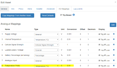
Go to Manage Assets >> Edit >> I/O Mappings and click Add
- Once you pick the Analogue number as per your OEM Server parameters you can set up the measurement configuration. There are a selection of preset Types available, or you can use a general number and conversion,
Note
if your number appears in Telemetry IO as an incorrect value, e.g. 250.0%, try changing the Conversion factor, this will change the converted figure in Telemetry IO but not the raw data in Telemetry.
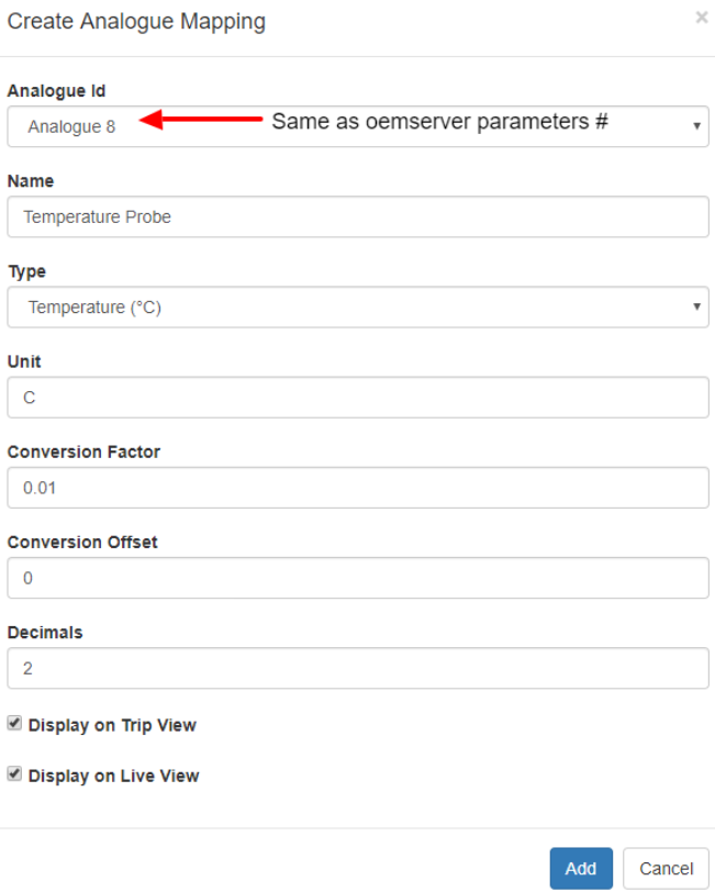
- Save, here you can also select whether the readings will appear in Trip view and Live view.
 |
 |
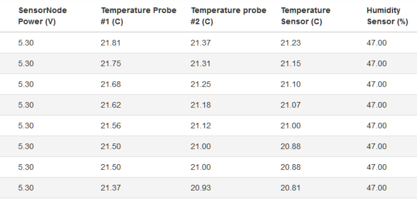
- Navigate to Assets >> Telemetry I/O and you can see the final converted readings. You can also graph the analogue values for custom time periods by going to Reports >> Fleet Reports >> Asset Analogue Graph.
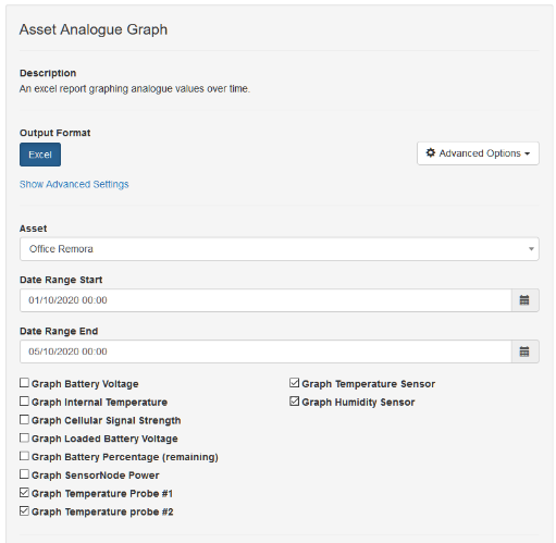
Temperature Alerts:
We can alert on the values like so Create Alerts on Analogue Values
Troubleshooting
If we can't see the readings in TG or 3rd Party platforms, we simply just need to check each 'link' in the chain. Often it's just a parameter that hasn't been checked. The links are:
SensorNode (working and beaconing) -> Gateway Device (correctly set up to read and pass on values) -> Tracking Platform setup.
Working through:
SensorNode:
This step usually isn't necessary, but its super quick and easy. To check the SensorNode is actually beaconing, you can just scan for available Bluetooth devices. On most phones, it will show up in the list as SN<serial> - i.e. SN123456. If it won't show up here, you can try downloading a 3rd party BLE scanning app like nRF Connect, and trying that one.
Gateway Device:
Particularly for 3rd party platforms, we can turn on Data Capturing on OEM. Often the tag data is truncated, but we can quickly check if we're actually getting scans.

Additionally, make sure to update your devices FW and Bluetooth FW (they are separate) - this commonly trips up users.
End Platform:
In TG, we can check the Telemetry (Assets -> Telemetry). Values will appear here if they are being sent by the device, irrespective of whether we have configured analogue mappings.
