Falcon - Getting Started

Written by Matthew Clark-Massera
Updated at February 2nd, 2023
Table of Contents
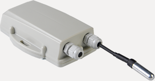
The Falcon Cellular is a super-smart, battery-powered tracking device in a rugged IP67 housing - in particular designed for asset location with temperature monitoring.
digitalmatter.com
Datasheet & High Resolution Images
Falcon Downloads
View the latest tech-specs and high resolution device images for the Falcon
This article will help you get up and running to test the Falcon.
| Sim Cards | Power Options | Getting Online | Housing |
| Default Parameters | Default I/O Mappings | Wiring in Sensors | Inserting an Ignition Line |
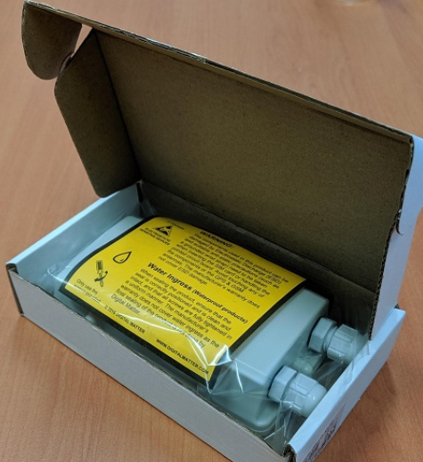
In the Box
You'll get a Falcon device with two glands for external probe wiring, the PCB is screwed into the housing with four screws, with six screws for securing the housing lid and an pre-installed seal for ensuring an IP67 seal.
One gland will be fitted with a stopper to prevent water ingress when no cable is fitted. DM can supply extra stoppers if both are going to be unused, or as replacements.
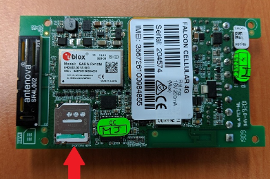
Inserting SIM Card
The Falcon uses a micro SIM card – form factor 3FF. The SIM holder is on the underside of the control board, so the device will need to be unscrewed and lifted out of the housing to insert the SIM.
Then open the SIM holder by sliding towards the edge of the board, and place the SIM with the keyed corner facing in and the SIM contacts orientated down to the main board. Then gently press the SIM cover back down and slide towards the middle of the board to latch.
To easily get up and running:
- The SIM should not have a PIN on it, unless you use the device specific PIN.
- The SIM should have credit or airtime.
APN AutoNet
For more information on Declaring APNs and the 4G AutoNet, see our knowledge base article here
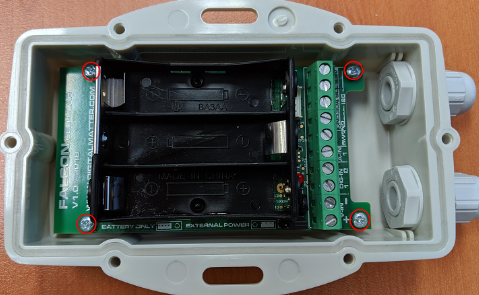
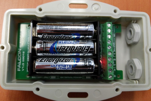
BatteriesBatteriesThe Falcon uses three AA LTC Batteries, and does not have reverse voltage protection so take care to insert the batteries with the correct polarity, the tabs being the negative terminals. Falcon Battery Recommendations and Estimates Please see our article here about selecting suitable batteries for the Falcon Once inserted, the LED should flash continuously. If it does not, it means the unit has not yet reset. In this case, remove the batteries for a minute or two to allow any residual charge to drain, and then reinsert them. Failure to reset the unit will prevent proper resetting of the battery life statistics. The Falcon is fitted with a Coulomb Counter which tracks the devices energy consumption. It is hard to predict the battery life of lithium batteries due to their flat discharge curve, the Battery Meter enables an accurate battery level to be determined for great features such as:
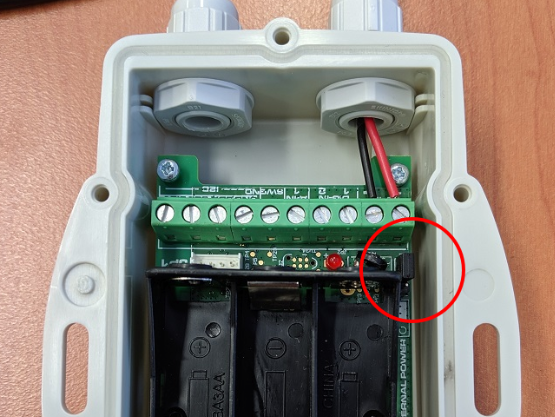
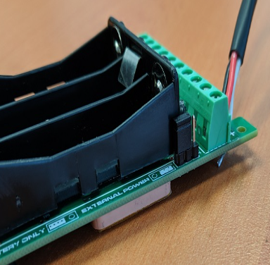
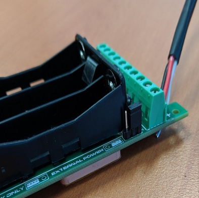
External PowerConnecting a Falcon to External PowerIf you want to wire the Falcon Cellular into an External power source and have the batteries as back up, it is a simple process of moving a jumper cap. Once you open the Housing of the Falcon, undo the screws at each corner to remove the PCB from the housing. You can then access the jumper cap as shown below.
As you can see printed on the PCB, the first position is to allow Battery Power usage, and the second to allow External power usage.
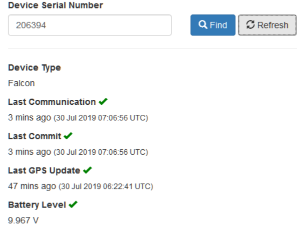
If you then check the oemserver.com/installer page after the next upload you'll see the voltage displayed in Battery Voltage:
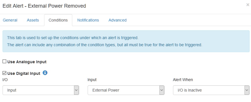
Setting up an External Power Removed Alert in Telematics GuruIn Admin > Alerts select 'New Alert Wizard' and select External Power Removed option. This will set an alert condition to trigger when the external power is removed from the Falcon. The Falcon measures External Power through it's Coulomb counter by monitoring the decrease in voltage over time.\ This means the external power alert will take a while to trigger after the fact since it needs to measure that the voltage has changed and is decreasing gradually, signifying battery power is being used.
|
Getting Online
Once the batteries are inserted, the internal LED will come on and flash. The device will do the following:
- Connect to the server: If the SIM card works the device will connect to the OEM Server and attempt to download any firmware and parameter updates then fetch fresh GPS aiding data.
- Get a GPS Fix: The device will attempt to get a GPS fix. You can speed this up by moving to an area with good GPS signal.
- Reconnect to the server: The device will attempt to connect again to upload the result of the GPS Fix.
If the device does not complete these steps in 10 minutes, it will go to sleep and try again on the next heartbeat or the next trip start. Go to www.oemserver.com/installer and search for the serial number to confirm that it has connected recently.
If the LED flashes but the Falcon does not connect, check the SIM is in the holder correctly and check that the SIM is working.
General Troubleshooting
Opening and Closing the Housing
Once online, all that remains is to seal the housing. Seal the device carefully to achieve the IP-67 rating. Ensure that the clear silicon seal is in good condition, is lying flat, and is not fouled by any plastic debris or other material.
- Close the housing, and gently squeeze it shut. Foam on the lid will compress against the batteries, holding them firmly in place.
- Tighten the 6 screws to a uniform tightness. On the first assembly, the screws may be quite stiff.
- If you wish to replace the batteries and open the housing, be sure to check that the silicon seal is in good condition before closing the housing again.
Default Settings
By default, the Falcon is set-up for trip tracking. For those familiar with the Oyster and Remora, the defaults are the same. The following default settings apply:
- Out of Trip: 12 hour heartbeats. This is a GPS point and an upload every 12 hours.
- In Trip:
- Start trip threshold of 250m
- Upload on trip start.
- GPS points every 2 minutes
- Upload every 30 minutes.
- End a trip after 5 minutes of no movement.
- Upload on trip end.
These settings and many more are configurable in the OEM Admin Interface. The defaults provide a good starting point but it is important to monitor and tweak your settings to ensure the battery life is acceptable. Incorrect settings can flatten the batteries quickly. Contact Support for help with this.
DeleteDefault I/O Mappings
The Falcon has the following digital inputs mapped by default, it is important to keep these in mind when mapping inputs to avoid clashes.
Digital Inputs
| Digital Mapping # |
Name |
|---|---|
| 0 | Ignition |
| 1 | Digital Input 1 |
| 2 | Digital Input 2 |
| 24 | Trip Status |
| 25 | Battery Flag |
Analogue Inputs
| Analogue Mapping # | Name |
|---|---|
| 1 | Supply Voltage |
| 3 | Internal Temperature |
| 4 | Cellular Signal Strength |
| 5 | Loaded Battery Voltage |
| 6 | Battery percentage remaining |
| 7 | Analogue Input |
| 8 | DM Temp Sensor 1 (Probe) |
| 9 | DM Temp Sensor 2 (Probe) |
| 10 | DM Temp Sensor 3 (Probe) |
| 11 | DM Temp Sensor 4 (Probe) |
| 12 | DM Ambient Temp Sensor |
| 13 | DM Ambient Humidity Sensor |
| 14 | MB7040 Ultrasonic Range Sensor |
Installation of I2C probes and sensors
Wiring Guide
please click here for a guide on how to connect Digital Matter probes and sensors to the Falcon
DeleteAdding an Ignition Wire to the Falcon
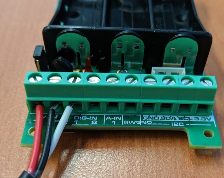
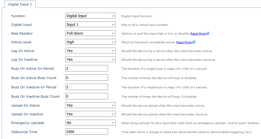
To enable accurate tracking when the Falcon is wired into a vehicle, there is the option to use Digital Input 1 as a wired ignition. First insert the wire ends into the terminals, from left to right the positive, ground and Digital 1/Ignition terminals as displayed below.
In OEM Server > System Parameters Set Digital Input 1 tab to active and change the following;
| Digital Input: | Set as Wired Ignition (0) to use the mapped ignition bit. |
| Bias Resistor: | Set to 'Pull down |
| 'Active Level: | Set To High |
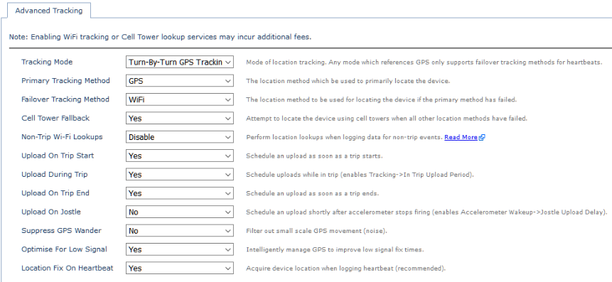
If you're planning to use the Falcon as an onboard vehicle tracker with the wired ignition, it's worth change the Tracking mode in 'Advanced Tracking' to 'Turn by Turn GPS Tracking' to mimic the tracking behaviours of a Dart2 device.