Hawk - Configure Pulse Count
Table of Contents
The Hawk can be configured to count pulses on digital inputs - for example to monitor a tipping rain gauge.
The fastest pulses the Hawk can count are approximately 40 Hz.
Ensure testing is performed on faster pulse rates to ensure they can be reliably counted.
Pulse counting will cause additional battery drain (compared to device sleeping) so needs to be factored in to battery life estimates.
Baseboard and Card Digital Inputs
It is important to recognise the distinction between the Hawk Base-board Digital Inputs and Hawk Plug in Card Digital Inputs.
- Base Board
- There is 1 x Digital Input on the Base-board.
- This is marked DIG-1 on the baseboard PCB.
- IO Cards
Card Name |
IO Marking |
Agtech 1 Card |
IO7 |
Agtech 2 Card |
None |
RS-1 Card |
IO7 |
Serial Card |
IO3 IO4 |
Bluetooth+ Card |
IO4 |
Digital Card |
IO5 IO6 IO7 IO8 IO9 |
Pulse Count on Baseboard Digital Input
Increment Count
Pulse Count Parameters
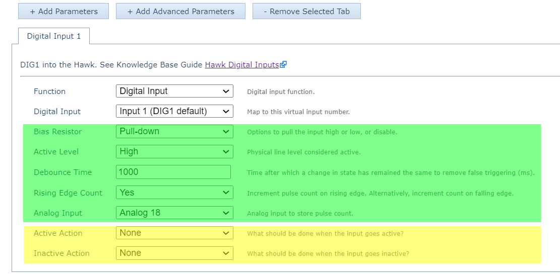
- Add the Digital Input 1 parameter tab.
- Set the debounce time (this should be shorter than your pulse width).
- Set Rising Edge count Yes/No for Rising/Falling Edge Count.
- Set the Analogue to write the pulse count to - in the above the count will be written to Analogue 18.
Actions
- In applications where digital inputs change infrequently, we may log and upload on a digital input change so we can be notified immediately.
- If we are counting many, fast pulses, we most likely want to disable all the actions shown in yellow - so they do not occur frequently. Even with logging disabled, we still increment the pulse count analogue in memory - we just don't log a specific record.
Upload Count Value Periodically
With the above parameters, the value is written to the specified analogue input (i.e. Analogue 18). It will only be uploaded when the device next uploads - either:
- On-device heartbeat.
- On-task upload.

If you are only looking at uploading pulse count (with no other action), you will need to do so by running a heartbeat.
If you run a Task without an Action, and without a GPS fix, the Task won't run. If you run a Task with a GPS fix but no Action, it will work.
Pulse Count on Card Digital Input
Increment Count
On your IO Card parameter tab - set the Rising Edge count as before.

Select Analogue Input

Choose the analogue input for the pulse count to be stored in the Hawk's Analogues.
Upload Count Value
Ensure Digitals Action 1 is an action for a Task.

The Task Schedule Period will be how often the current pulse count is logged to a record. Maybe we want to see a snapshot each hour to track rainfall over time and which periods saw more rain.
The Task upload period will be how often the total pulse count is uploaded to the server - i.e. upload daily.
Quick Pulse Count Updates During Periods of Rapid DI Changes
In some instances, you may want a device to check in infrequently, but if the Digital Input begins to change rapidly, you may want the device to upload pulse counts more frequently.
This is how you achieve that functionality.
Behaviour outline:
- Device uploads infrequently (e.g. twice per day)
- DI Changes (based on a pulse count)
- Begins a Task (which includes a 30s Timeout)
- Accumulates pulse count.
- Uploads.
- DI Changes again, repeat.
Hardware Requirement
Please note, you will need a Hawk IO Card that contains a Digital and an Analog Input.
- Set up pulse counting on a Card Digital Input as per the above instructions.
- Set up a Digital Input Monitor, and select the relevant Card DI to monitor (the DI that you are pulse counting on).

Configure the “Run Task on Active” to be a task (in this instance, Task 2)
- Configure “Task 2” as below:

- Configure Analogs Action 1 as below. The power on delay will correspond to "how often" you want to save the pulse count that is being incremented. For the Analog offset, please select an Analog that is not in use. No valuable data will be saved there.

- Configure Digitals Action 1 as below. Select the Analog you would like to save your pulse count to.

Behaviour in the event of Power Loss
The total count is saved to flash memory on the device, so it is maintained in the event of power loss.
- If the Hawk host is counting on the Hawk Digital Input, the count is saved at least every 5 minutes.
- If the IO Cards are doing the counting, the value is saved at least every 10 seconds.
Manually Set Digital Input Counter
We have introduced the ability to manually set the value of the pulse count via an async message or a Task/Action.
Async 0x0103 – Set Digital Input Counters
The below information is from OEM WebAPI -2.0.
Requires Hawk FW v1.6+, Agtech1 card FW v1.9+, and/or RS card FW v1.5+.
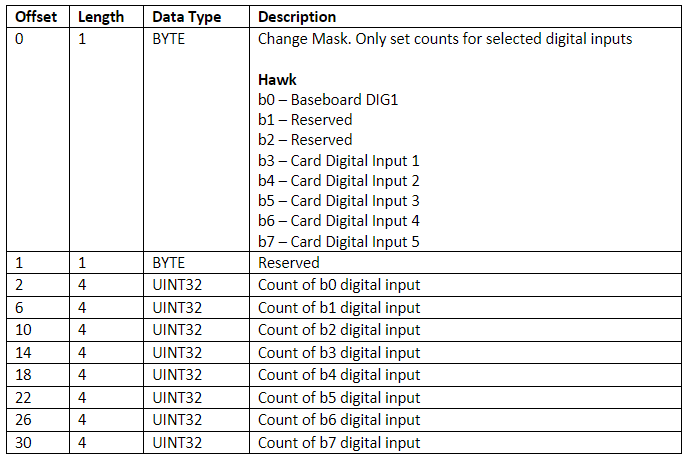
Example: Set Baseboard Digin to 400 and Reset Card Dig In 1 to 0.
Async code:
{
"MessageType":259,
"CANAddress":4294967295,
"Data":[9,0,144,1,0,0,0,0,0,0,0,0,0,0,0,0,0,0],
"ExpiryDateUTC":"2024-11-25T18:25:43.511Z"
}

9 - represents the change mask – Essentially selecting which digital input counters you would like to target with the async. In this case we are targeting the baseboard Digin (b0) and Card Dig in 1 (b3) 00001001 = 9
0 – Reserved byte
144,1,0,0 – This UINT32 value is made up of 4 bytes. 400 in 32bit binary is 00000000 00000000 00000001 10010000. This can be written as 0,0,1,144. This is big endian, and the async payload structure is little endian.Therefore, it is written as 144,1,0,0.
0,0,0,0 and 0,0,0,0 – These represent the count of b1 and b2. Because we aren’t changing these, we can write whatever we want here, but we do need to write the 8 digits.
0,0,0,0 – This represents the count of b3. Because we are setting it to 0, keep them all zeros.
Set Card DI Count Action
Please Note!
Please note, that this only applies to Digital Inputs on the IO Card, not the DI on the Baseboard.
Requires Hawk FW v1.6+, Agtech1 card FW v1.9+, and/or RS card FW v1.5+.
Configure the below action appropriately for your use case. In this instance, below:
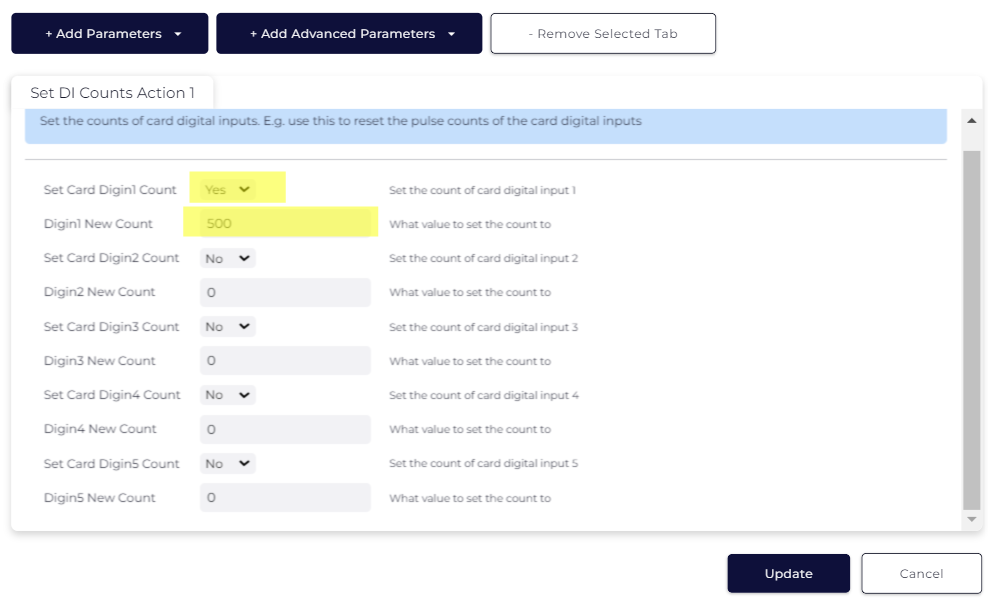
This Action sets the Digital Counts, which are invisible variables saved to the IO card.
In order to save these counts to Analogs (to be reported by the device to an end platform), a second Action is needed.
Please see below:
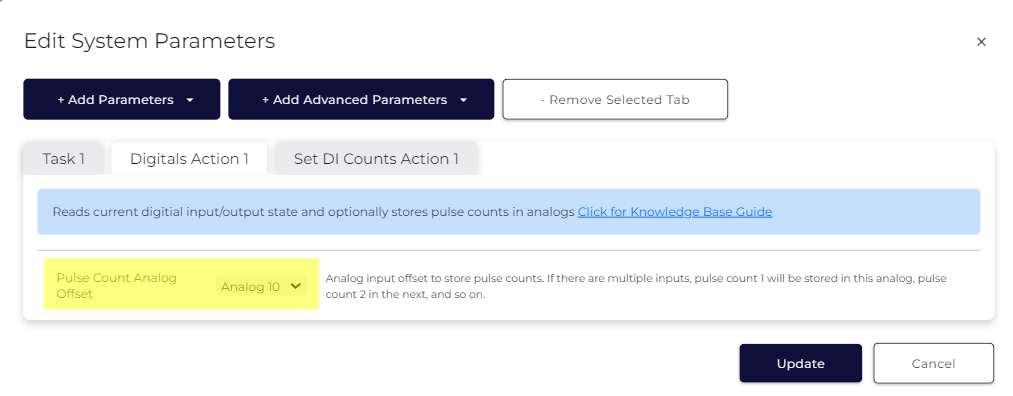
This saves the Digitcal Counts to an Analog, which will then be reported the next time the device uploads.
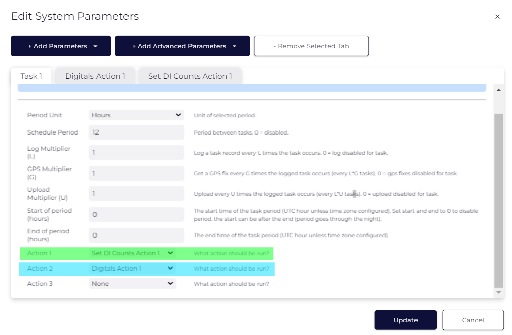
The final step is to schedule a Task that runs both of the above actions, in this order:
