G62 - Getting Started

Written by Matthew Clark-Massera
Updated at February 3rd, 2023
Table of Contents
The G62 is a compact 4G GPS tracking device with a variety of inputs and outputs to cater for the most demanding applications.
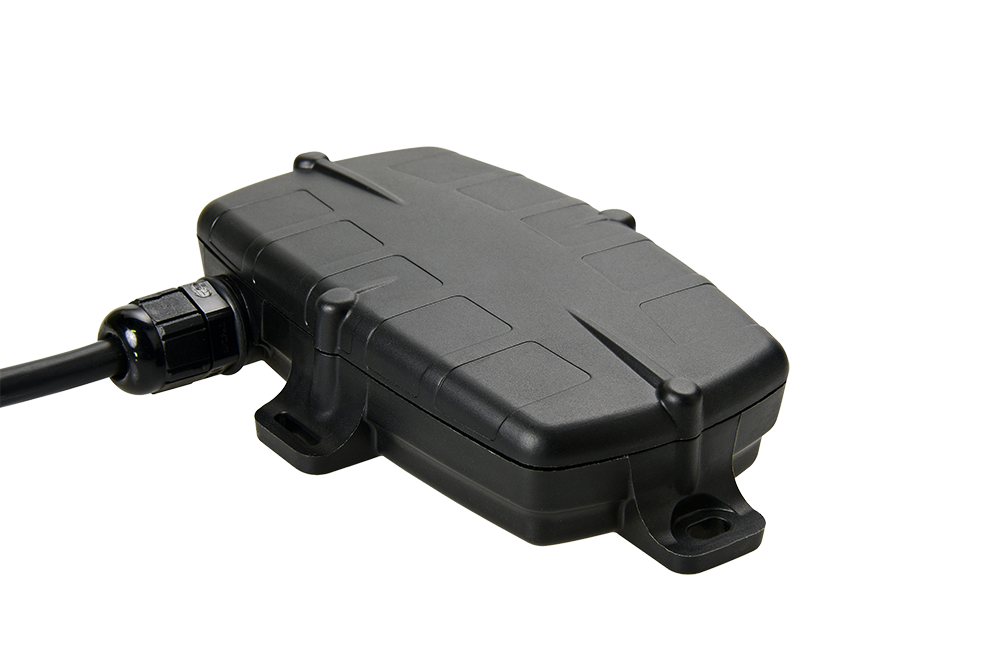
The 4G modem allows for operation on both Cat-M1 and NB-IoT networks. Its rugged housing is IP67 rated to withstand the harshest environments, without sacrificing tracking and communications performance. With the internal GPS and cellular antennas installation is a breeze. The internal backup battery provides alerts and tracking operations even when external power is removed.
digitalmatter.com
See the G62 product page on digitalmatter.com for more specifications. This guide will help you get up and running with the G62.
Datasheet & High Resolution Images
G62 Downloads
View the tech-specs and high resolution device images for the G62
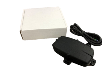
In the Box
You'll get a compact box containing the G62 and a small packet containing the 6 housing screws.
Setting it Up
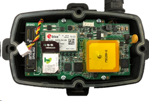
Sim Card installation
The G62 takes a 3FF Micro SIM card. The G62 may be damaged by electrostatic discharge if not handled correctly so ensure adequate static precautions are taken. Consider wearing an anti-static wrist guard and avoid touching the antennae and any of the electronic components on the PCB. Take special care not to touch the ceramic GPS antenna as static can damage the sensitive GPS circuitry.
The SIM holder is located on the top side of the main PCB.
- Unplug the battery and remove any external power connections.
- Slide the locking mechanism on the SIM holder to the “unlock” position, and lift the hinged portion of the SIM holder.
- Insert the micro SIM into the holder with the keyed corner orientated away from the hinge and the SIM contacts orientated down to the PCB (see example above).
- Close the SIM holder and slide the locking mechanism to the “lock” position.
To easily get up and running:
- The SIM should not have a PIN on it, unless you use the device specific PIN.
- The SIM should have credit or airtime
- The SIM should use one of the APN's built into the firmware. Otherwise contact support about APN setup.
Remember
Make sure once you're online, to declare your APN in the Admin parameters to ensure if you lose the network connection the device knows where to re-connect, and doesnt take time and battery life scanning through all known frequencies
APN AutoNet
For more information on Declaring APNs and the 4G AutoNet, see our knowledge base article here
Battery Installation
The battery should be provided disconnected inside the housing. The battery plug is a three-way connector on the top side of the PCB.
- Insert the battery plug into the connector. It should only be possible in one orientation.
- The LED on the board will light up and flash if the battery has sufficient charge. Batteries are supplied fully charged.
- Route the battery wires into the space between the GPS board and the housing. Take care to avoid trapping the wires when sealing the device.
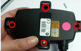
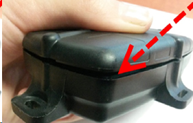
Closing the Housing
Ensure that the main PCB is secured to the housing with the 4 small PCB screws and that the SIM is inserted as above. Ensure that the device is online before sealing it. The seal should be the latest Digital Matter clear silicon seal to ensure the IP rating of the housing.
- Ensure that the seal is in the base and lying flat, and that there is not dust or dirt on the seal.
- Ensure the battery cable will not be pinched by the lid and place it onto the base.
- Insert the 4 x 20mm housing screws.(BN 82428 3.5x20mm
- Hand tighten the screws to a uniform tightness.
- Ensure that the cable gland is tightened around the cable.
 |
 |
Please make sure that you take extra precautions to ensure that the device has been sealed adequately when it will be installed in environments where it is exposed to the weather or water or liquid spraying. The Digital Matter manufacturer’s warranty does not cover damage due to water ingress as the final installation is not performed by Digital Matter.
Device Mounting & Installation
The housing has mounting holes for screws, bolts or cable ties. There are a few considerations for the final mounting position of the G62:
The G62 has been engineered to have the best possible GPS reception. It will work from inside engine bays, body panels, under dashboards and other places where other GPS devices simply fail to operate reliably.
Although the G62 will work in these locations it is always advisable to install the G62 where it is able to get signals from the GPS satellites, with the optimum position being a location with a clear 180-degree view of the sky.
Instructions for Mounting
For greater detail on the mounting process, check out the knowledge base article here
Note
The Dart, Dart2, G62 LTE & LoRaWAN and G100/G120 models all have 200mA fuses installed on the PCB for external power inputs. Digital inputs (including ignition) and switched ground outputs do not have integrated fuses, and are not specifically required by design, but may be installed to protect against external wiring faults.
The Fuses are self-resetting and do so when the fuse cools down. If the fault that is causing the fuse to trip is still present, it will require the device to be removed from power sources.
This means that the installer does not have to set up their own fuses for the device..
Troubleshooting Steps
See here for tips for if your device isn't connecting
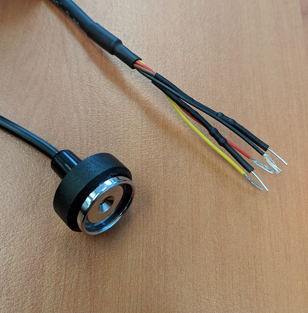
Wiring Harness
| Pin # | Colour | Function | Notes |
| 1 | Red | Voltage Input | 8-36 Volts DC External power |
| 2 | Black | Ground | Main Ground |
| 3 | White | Ignition | 0-48 Volts DC, permanent internal pull down |
| 4 | Blue | Digital Input 1 | 0-48 Volts DC, configurable pull down |
| 5 | Yellow | Digital Input 2 | 0-48 Volts DC, configurable pull down |
| 6 | Brown | iButton | iButton input |
| 7 | Green | Switched Ground Output | Low side Switch. Use with a relay, LED or buzzer |
Default Parameter Settings
The G62 will operate with default settings out of the box. These can be changed using the OEM Admin interface. The defaults include:
- Hourly Heartbeats: the device will log a heartbeat record, connect to the server, and refresh its GPS data every 60 minutes.
- Wired AND Emulated Ignition: by default, the G62 will track a trip if either the ignition wire is pulled high or movement is detected. The setting can be changed to do one or the other, or continue to use both.
- Inputs: inputs are pulled up internally and are active low. This means you can connect pull to ground switches or contacts. The bias can be set to pull up, down or neither. They can be set too active high or low and the debounce can be changed.
- Output: the output is not used by default
Default I/O Mappings
Digital inputs, analogue inputs, and various 'statuses' (e.g. GPS interference detected) can be mapped to device Digital inputs
The G62 has the following digital inputs mapped by default, it is important to keep these in mind when mapping inputs to avoid clashes.
Digital Inputs
| DI Number | Meaning | Comment |
| 0 | Ignition | |
| 1 | Digital Input 1 | Physical digital input 1 is mapped here by default, but it can be remapped elsewhere. |
| 2 | Digital Input 2 | Physical digital input 2 is mapped here by default, but it can be remapped elsewhere. |
| 5 | GPS Interference | GPS Interference indicator is mapped here by default, but it can be remapped elsewhere |
| 6 | GPS Jamming | GPS Jamming indicator (signal lost) is mapped here by default, but can be remapped |
Driver ID Options
The G62 can use the Dallas iButton readers as well as MiFare, EM4001 125kHz and HID cards. See here for more Driver ID options.