G150 Accelerometer Sampling
Table of Contents
Application
The G150 can be configured to capture accelerometer data continuously. This is useful for intensive kinematic analyses. By continuously sampling the acceleration of a device, it is possible to reconstruct the orientation and movement of an asset, or assess the impacts, vibrations and forces endured by it. In doing so, it is possible to model the dynamics of the asset to deduce its kinematic state or behaviour at any given time.
Although accelerometer data sampling is as simple as continuously reporting the multi-axis acceleration of the device, intensive data analysis is required by the user to interpret the data.
System Parameters
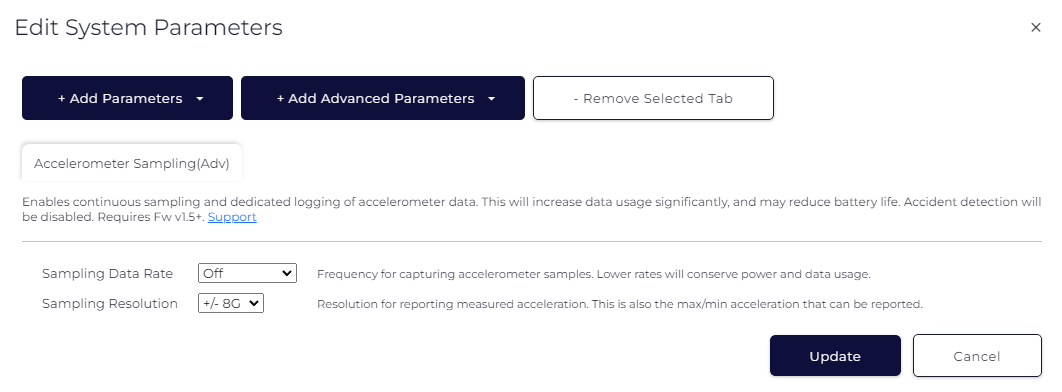
Accelerometer sampling is configured in the ‘Accelerometer Sampling’ tab of the Advanced System Parameters. By default, the sampling is off. This is achieved by setting the ‘Sampling Data Rate’ parameter to 'Off.
When sampling is enabled ('Sampling Data Rate' parameter set to a value other than 'Off), the accelerometer resolution is selected using the ‘Sampling Resolution’ parameter. This is +/- 8G by default.
Importantly, the device cannot use both accident detection and accelerometer sampling. If accelerometer sampling is enabled, accident detection will automatically be disabled.

Sampling Data Rate
There are 6 sampling data rates that can be selected. Setting the data rate will determine how many accelerometer samples are measured and saved per second. E.g. 25Hz will measure and save 25 samples every second, or 1 sample every 40ms.
The data rate should be carefully selected, as it will affect a few factors:
- The amount of data the device stores and uploads. The higher the rate, the more data the device will produce.
- How long the device will last on the backup battery. The higher the rate, the shorter the battery life will be.
To minimise the impact on data usage and battery life, the lowest possible data rate should be selected for the application. What is the lowest rate that can be set to satisfy the needs of the application?
The G150 has been optimised to preserve battery life while continuously capturing accelerometer data. However, the sleep current of the device will increase for higher sampling rates. This should be taken into consideration when estimating how long the battery will last if the device is not connected to external power.
| Sampling Data Rate | G150 Sleep Current* | Daily Accelerometer Data** |
| Off | 8uA | 0kB |
| 1.6Hz (ULP) | 12uA | 500kB |
| 3Hz (ULP) | 13uA | 1MB |
| 6Hz | 16uA | 2MB |
| 12.5Hz | 17uA | 4MB |
| 25Hz (ULP) | 14uA | 8MB |
* Sleep current measured when operating on battery power only (no external power connected) and when in Periodic Tracking Mode.
** Only considers accelerometer data, and is approximate. Actual data usage will be higher because of other tracking data from the device.
Sampling Data Rates that are marked by ‘(ULP)' indicate that the accelerometer is operating in Ultra Low Power Mode, compared to the standard Low Power Mode of the other data rates. It is for this reason that the sleep current for these sampling rates is favourable compared to those of the other data rates.
NB. The sampling rate will have an effect on the responsiveness of the device. For example, quick accelerometer transients might be missed for very low data rates. This could result in delayed device wakeups or cause the device to miss wakeups altogether.
Sampling Resolution
Each accelerometer sample that is measured contains a data value for each of the three axes: X, Y and Z.
The reported accelerometer values will vary depending on the selected resolution. The resolution determines:
-
The range of accelerations that can be measured in each direction.
The higher the value, the greater the range of accelerations that can be reported. E.g. +/- 2G means the accelerometer will not be able to report values of more than +2G or less than -2G. Values outside of this range will saturate and be reported as +/- 2G.
-
The resolution per bit.
The higher the value (E.g. +/- 8G being much higher than +/-2G), the more granular the resolution per bit, so the reported acceleration will be more accurate. See Data Type Conversions below.
Therefore, there is a trade-off between the range and the bitwise resolution. The greater the range, the lower the bitwise resolution. Users should select a value that best suits their specific application.
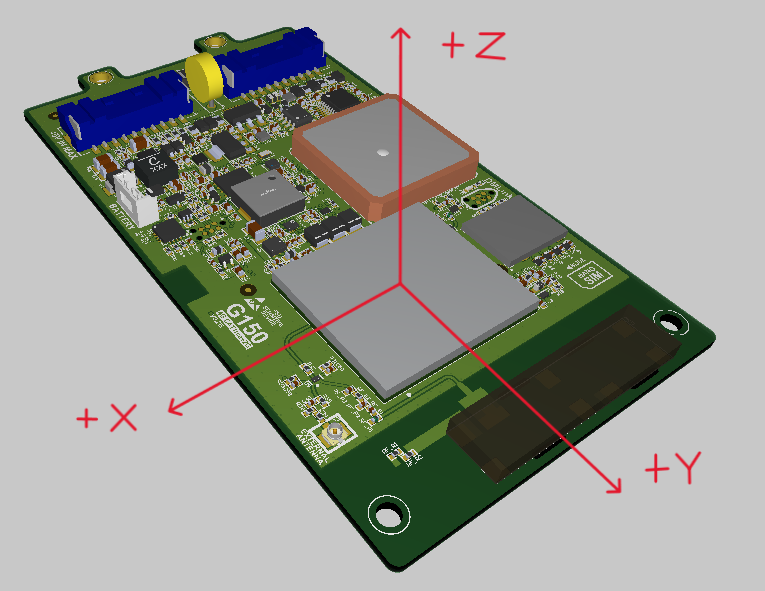
Orientation
The G150 accelerometer axes report data according to the following orientation:

Data Type Conversions
Accelerometer sample data is reported using FID 37. Please refer to the DM Data Fields document for specifics on the data format.
The X & Y axes record the following raw accelerometer values:
| Axis | Data Size (signed 2's complement) | Raw Data Range |
| X | 11 bits | -1024 to 1023 |
| Y | 11 bits | -1024 to 1023 |
| Z | 10 bits | -512 to 511 |
The raw accelerometer data is a scaled measurement of the actual acceleration. The actual acceleration in G's is calculated by multiplying the value by the resolution, according to the following table:
| Axis | +/- 2G Resolution | +/- 4G Resolution | +/- 8G Resolution | +/- 16G Resolution |
| X | 1.953 mG / bit | 3.906 mG / bit | 7.813 mG / bit | 15.625 mG / bit |
| Y | 1.953 mG / bit | 3.906 mG / bit | 7.813 mG / bit | 15.625 mG / bit |
| Z | 3.906 mG / bit | 7.813 mG / bit | 15.625 mG / bit | 31.250 mG / bit |
E.g. The X axis reporting a raw value of 467 for a resolution of +/-8G will correspond to an actual acceleration of 867*(0.007813) = 3.65G
Data Field Integration
Accelerometer sample data is reported using FID 37. Please refer to the DM Data Fields document for specifics on the data format.
When accelerometer sample data is logged, the log reason 25 is used (Sensor Value Elapsed Time). Please refer to the DMT Log Reasons document for more information.
NB. Telematics Guru does not yet support FID 37 for acceleration sample data. Therefore, devices will not be able to commit records successfully if devices are pointed to Telematics Guru.
