G100 - Getting Started
Table of Contents
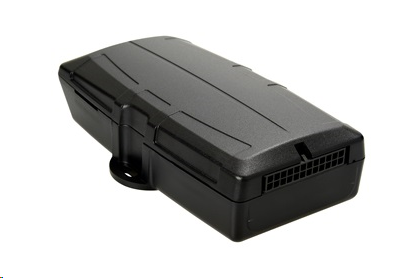
The G100 is a compact 2G or 3G GPS tracking device to cater for the most demanding applications. The stand out feature of the G100 is the FlexiCard slot. This allows for the most flexible expansion options in the industry – including an Iridium satellite modem, Wi-Fi and other interface options.
The G100’s compact housing contains the GPS and cellular antennas. All of the G100’s functionality is exposed through a 24 wire connector, allowing for quick and simple installations. This includes ignition, four digital inputs, two digital outputs, iButton (1-wire Dallas tag) and the DMCAN expansion harness. The internal backup battery provides alerts and tracking operations even when external power is removed.
The G100 can simultaneously use GPS and GLONASS satellites, providing double the number of positioning satellites available. It uses offline satellite aiding technology for faster acquisition and more accurate and reliable tracking in locations where other devices just give up.
In the Box
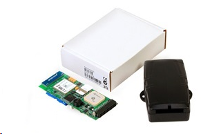
You'll get a compact box containing the G100, with an 800mAh battery stuck to the PCB, and an 18 or 24 wire harness.
The medium harness has 18 wires and the full harness has 24 wires. If custom functionality is required, wires may be added to the 18 wire harness.
Setting it Up
SIM Card
The G100 takes the standard 2FF SIM card. The SIM holder is on top of the main board, between the modem and GPS antennas. When handling the G100 take care not to touch the GPS antenna, to minimise the risk of damaging the sensitive GPS amplifiers with static discharge.
Ensure the battery and external power are disconnected to ensure the mobile data connection is not active.
Slide the SIM into the holder from the edge of the PCB. Ensure the SIM is fully inserted.
The SIM should be inserted with the keyed corner facing out of the PCB, and the SIM contacts orientated down to the main board.
To easily get up and running:
- The SIM should not have a PIN on it, unless you use the device specific PIN.
- The SIM should have credit or airtime
- The SIM should use one of the APN's built into the firmware. Otherwise contact DM about APN setup. It is possible to set APN's by SMS
Battery
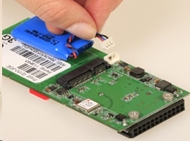
The battery should be stuck to the underside of the PCB. Do not move it. The battery plug is a three-way connector on the underside of the PCB.
- Tilt the PCB, lifting it out of the housing. Raise the edge opposite to the SIM card. Take care to avoid touching the GPS antenna.
- Insert the battery plug into the connector. It should only be possible in one orientation.
- The LED on the board will light up and flash if the battery has sufficient charge. Batteries are supplied fully charged.
- Place the PCB back into the housing. See the next section for more details
Housing Assembly
Once the SIM and batteries are installed and the device is online, the housing can be closed. The lid of the housing clips into the base. No screws are required. To close the housing, line up the top and bottom parts. Push the housing together firmly.
Locate the PCB on the base. There are a number of fingers around the edge of the PCB that will locate it. Place the lid on the base, and gently squeeze one side to engage the clips. Squeeze the other side to engage the remaining clips.
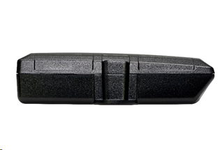
The housing can be opened by prying the lid from the base using a flat screw driver. A wide screw driver will ensure the housing is not marked. Locate the slot for the screw driver on the side of the housing. Insert the screw driver and twist to pry the housing apart. Be careful with the clips.
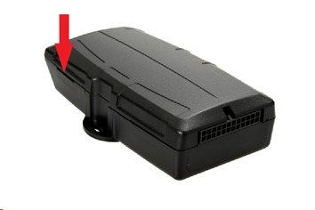
Device Installation
The G100 can be mounted on the asset to be tracked using screws, bolts, cable ties, or industrial adhesives. The device is not IP67 rated, so be cautious when installing it in the engine bay or in an exposed location. See section 6 for the wiring diagram.
The high performance GPS and GSM antennas allow the device to be concealed. However, always check the GPS and GSM performance after installation.
Getting Online
The battery should come pre-charged. Once you insert it, the internal LED will come on and flash. If the SIM card works and there is sufficient charge in the battery, the device will connect to the OEM Server. To confirm it has connected, go to www.oemserver.com/installer and search for the serial number. The LED will flash slowly at first then when it opens a connection to the server it will flash fast. Once data is sent, it will go solid briefly and revert to flashing fast. When the device goes to sleep, the LED will switch off. If the battery is too low, use the harness to provide external power. If the LED flashes but the G10 does not connect, check the SIM is in the holder correctly and check that the SIM is working.
Default Settings
The G100 will operate with default settings out of the box. These can be changed using the OEM Admin interface. The defaults include:
| Hourly Heartbeats | The device will log a heartbeat record, connect to the server, and refresh its GPS data every 60 minutes. |
| Wired AND Emulated Ignition | By default, the G100 will track a trip if either the ignition wire is pulled high or movement is detected. The setting can be changed to do one or the other, or continue to use both. |
| Inputs | The inputs are pulled up internally and are active low. This means you can connect pull to ground switches or contacts. The bias can be set to pull up, down or neither. They can be set too active high or low and the debounce can be changed. |
| Outputs | The output is not used by default |
| Driver ID | The G100 can accept Driver ID inputs from the DM RFID reader, iButton reader, 5 Digit Keypad, or CAN Console. |
G100 Harness Diagram
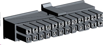
The harness is a 24 way Molex connector with varying numbers of wires exposed. Two wire harness variations exist: the medium and the full harness. The medium harness has 18 wires and the full harness has 24 wires.
# |
Colour |
Medium Harness |
Full harness |
Function |
Notes |
|---|---|---|---|---|---|
1 |
Grey |
Y |
Y |
iButton |
iButton Input |
2 |
Black |
Y |
Y |
Ground |
Optional ground Point (useful for iButton) |
3 |
Purple |
Y |
Y |
5V DM CAN Rail |
Pin 3 of 4 way Molex. Powers Peripherals |
4 |
Brown |
Y |
Y |
Digital Input 4 |
0-48 Volts DC |
5 |
Green/Black |
Y |
Y |
Digital Input 3 |
0-48 Volts DC |
6 |
N/A |
N |
Y |
Flexicard I/O 4 |
Line to the Flexi Card |
7 |
N/A |
N |
Y |
Flexicard I/O 3 |
Line to the Flexi Card |
8 |
N/A |
N |
Y |
Flexicard I/O 2 |
Line to the Flexi Card |
9 |
N/A |
N |
Y |
Flexicard I/O 1 |
Line to the Flexi Card |
10 |
Green |
Y |
Y |
Switched Ground 2 |
Low Side Switch. Use with a relay, LED, or Buzzer |
11 |
Yellow |
Y |
Y |
Switched Ground 1 |
Low Side Switch. Use with a relay, LED, or Buzzer |
12 |
Black |
Y |
Y |
Main Ground |
Main Ground Point. Ensure grounded |
13 |
Green |
Y |
Y |
DM CAN_N |
Pin 2 of 4 way Molex |
14 |
Yellow |
Y |
Y |
DM CAN_P |
Pin 4 of 4 way Molex |
15 |
Black |
Y |
Y |
Ground |
Pin 1 of 4 way molex. ground for peripherals |
16 |
Blue |
Y |
Y |
Digital Input 2 |
0-50 Volts DC |
17 |
Pink |
Y |
Y |
Digital Input 1 |
0-50 Volts DC |
18 |
N/A |
N |
Y |
Flexicard I/O 6 |
Line to the Flexi Card |
19 |
N/A |
N |
Y |
Flexicard I/O 5 |
Line to the Flexi Card |
20 |
Black |
Y |
Y |
Ground |
Optional Ground Point |
21 |
Purple |
Y |
Y |
RS232 Rx |
RS232 Receive line |
22 |
White/Black |
Y |
Y |
RS232 Tx |
RS232 Transmit Line |
23 |
White |
Y |
Y |
Ignition |
0-50 Volts DC. permanent internal pull down |
24 |
Red |
Y |
Y |
Voltage Input |
8-45 Volts DC External Power |
Driver ID
The G100 can read Driver ID tags from the following reader types:
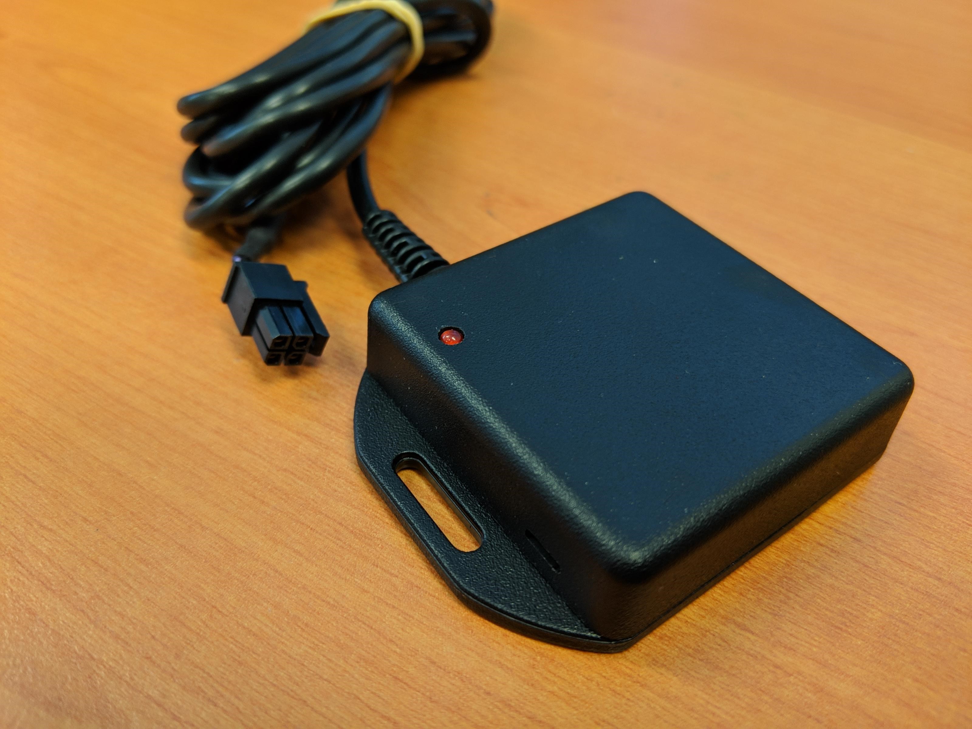
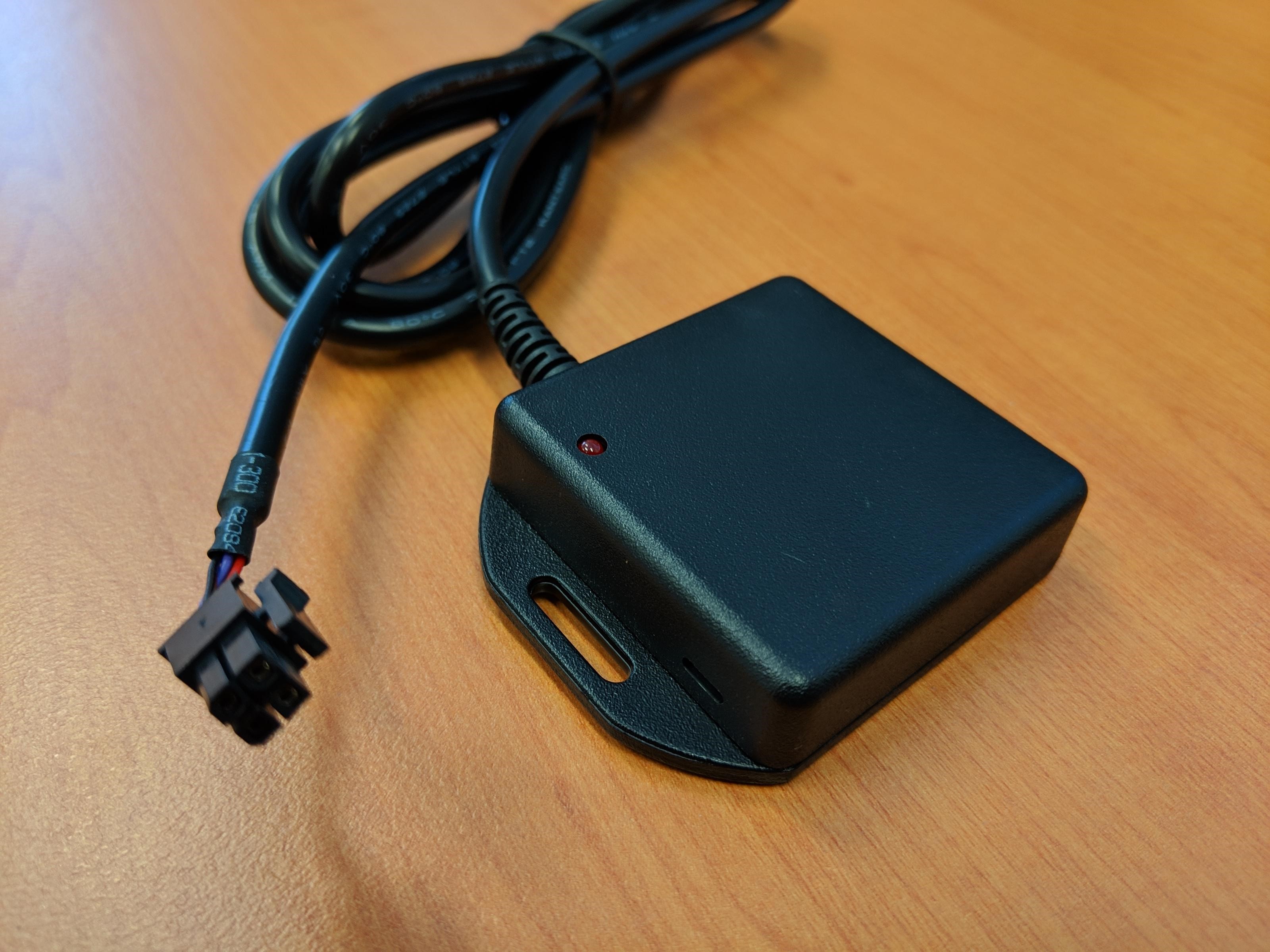
- DM RFID Reader: read 125kHz RFID tags or cards.
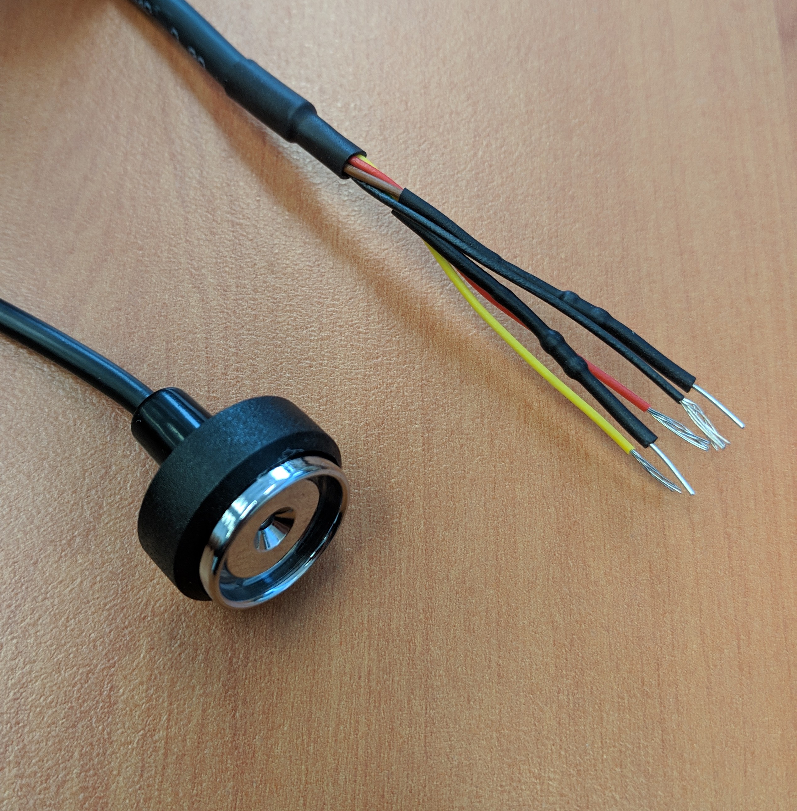
- iButton Reader: read Dallas iButton tags.
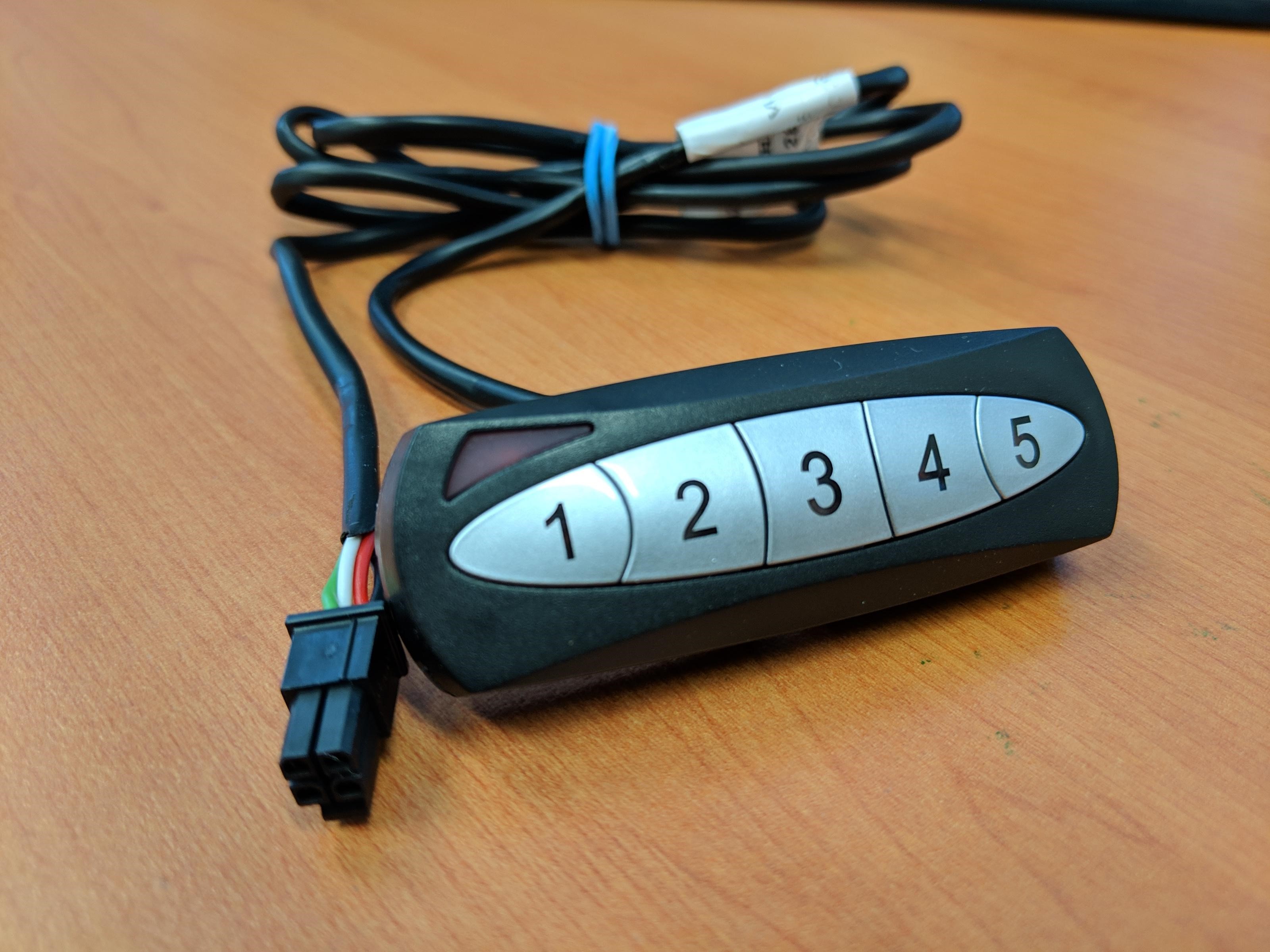
- 5 Digit Keypad: accept 4 or 5 digit PINs
- CAN Console: read 125kHz RFID tags or cards.
 |
 |
 |
 |
