Monitoring Door Open/Close
Table of Contents
Often the 'status' of a door, window, gate or other needs to be remotely monitored. This is to track things like unauthorised access to a room, building or container (perhaps with precious cargo inside).
Our devices have the ability to do this via multiple methods:
- Connecting a reed switch to one of the digital inputs (most reliable, recommended method)
- Based on the accelerometer activity
- Use of a BLE Tag.
Reed Switch + Digital Input
Applies to
| Device | Firmware Version |
| Dart2/Dart3 | All FW Versions |
| G62/G70 | All FW Versions |
| G120 | All FW Versions |
| G150 | |
| Hawk | All FW Versions |
The above list are DM devices with a digital input.
It is likely that the Hawk will be the best choice for detecting door open/close in a stationary setting like a building/worksite - given the 2 x D Cell battery option.
What is a reed switch?
The reed switch is an electrical switch operated by a magnetic field.
In it's most basic form, the switch consists of a flexible ferromagnetic metal contacts inside a sealed glass tube. When a magnet is brought close to the 'reeds', the reeds move so that they come into contact, closing the switch. You can often hear a slight click sound when this happens if you hold the switch to your ear.
The switch shown at 1:30 is a common form of switch that would be used, Single Pole Double Throw (SPDT) with a Normally Open (NO), and Normally Close (NC) contact.
"Normally" refers to when the switch is not affected by a magnetic field (no magnets nearby)
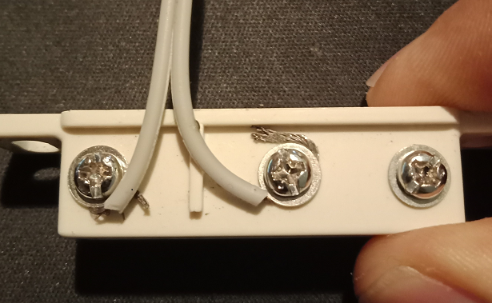
Here is an example
The principle of operation is the same for all reed switches, though they come in different mount options/casings etc, and at varying costs. The one pictured is built for a garage roller door, and fits into the corrugations easily.
The 3 screw terminals are the Common, NO and NC contacts.

Set Up
There is more than 1 way to set up a reed switch and the device to achieve the same result. As long as when the door is open/closed, the magnet moves near/away from the switch, causing the state of the switch to change, we can monitor it.
In this example we will consider the following:
- Door closed - magnet is in contact with the reed switch. We want the device digital input to be off/'0' in this scenario
- Door open - magnet is away from switch
*The opposite (i.e. door is closed and the magnet is not in contact with the switch, and vice versa) can also be catered for but we will not discuss it here. The physical requirements of the application might dictate this is needed. Contact DM support if you are unsure.
It is important that we can detect if there is a break in the cable (due to damage, or someone cutting it). So operation will be as follows
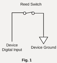
Normally Open (NO) on reed switch connected to Digital input on device, Common connected to Ground on device. When the door is closed, the magnet is close to the switch. This is not the 'normal' position for the switch, so it is closed.
This is illustrated in Figure 1 below
 |
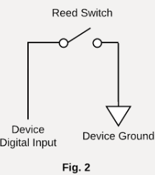 |
Then when the door opens the magnet moves away and the switch is in the 'normal' position - so it is open, and we want to detect this as 'on' for our device input.
This is illustrated in Figure 2 above.
Note how this breaks the circuit to register a door open. So similarly, if the cables were cut/damaged - 'open' would also be registered. The door might not actually be open but this helps in detecting tampering/faults.
Device Setup
The Digital Input which the reed switch was connected to needs to be set up.
Full details here: Digital Inputs Introduction
Below is the configuration for a cellular device, the equivalent configuration for LoRaWAN devices can be achieved using the configuration tool.

Bias Resistor and Active Level.
We must set the Bias Resistor to 'hold' the state of the input either high or low when nothing is connected, otherwise the state is undefined.
Pull-up and High means the behaviour will be:
- Door closed, magnet near switch, as in Figure 1
- There is a path to ground and the input is "low", so registers a '0' (since the active level is High', low means not active)
- Door open, Figure 2 applies
- There is no path, so now nothing is connected to the Device Digital Input. The bias resistor pulls the line high, which is logged as active '1' on the device.
Upload on Active and Inactive
We will get an immediate notification sent to the server if the door opens/closes.
Telematics Guru Configuration - I/O Mappings, Alerts, Reports
To display in Telematics Guru, do the following:
Set up the I/O Mapping
Setting up the I/O mapping simply gives a meaningful name to the digital input. The previous step ensures that data will be sent to TG when the door opens or closes, but now we need to put it in an easily readable format.
- Go to Assets -> Manage Assets
- Click the Asset Name you want to edit (or do this when creating your asset)
- Go to I/O Mappings
- Create the Mapping

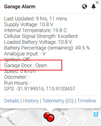
The active state (1) is Open, and inactive (0) is closed (as per OEM set-up)
Display on Trip view results in the status being available on the map
To send alerts via Telematics Guru, we simply need to set up an alert that is sent when the Digital Input is activated.
This can be done using the "Advanced" Alert creator, found under Admin -> Alerts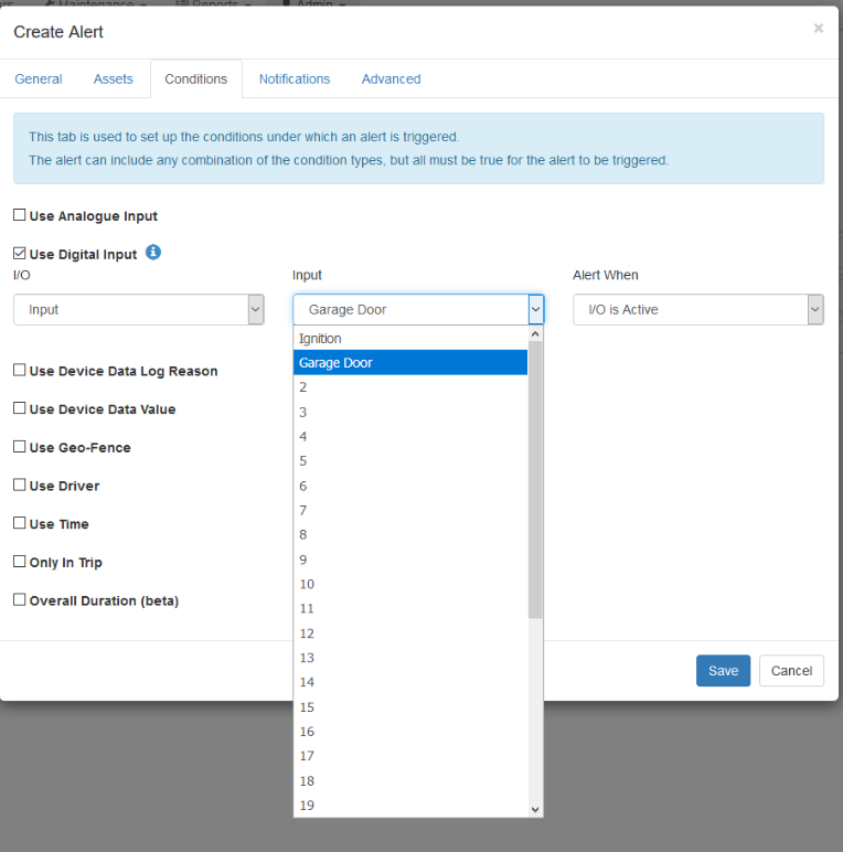
If the relevant asset is selected in the "Assets" Tab of Create Alert, the name given in the I/O mapping will appear as shown in the image.
An alert can also be sent when the door closes again, so the user is notified when everything is back to 'normal' Under the Advanced tab of the alert setup, simply select this option and fill in the message you would like.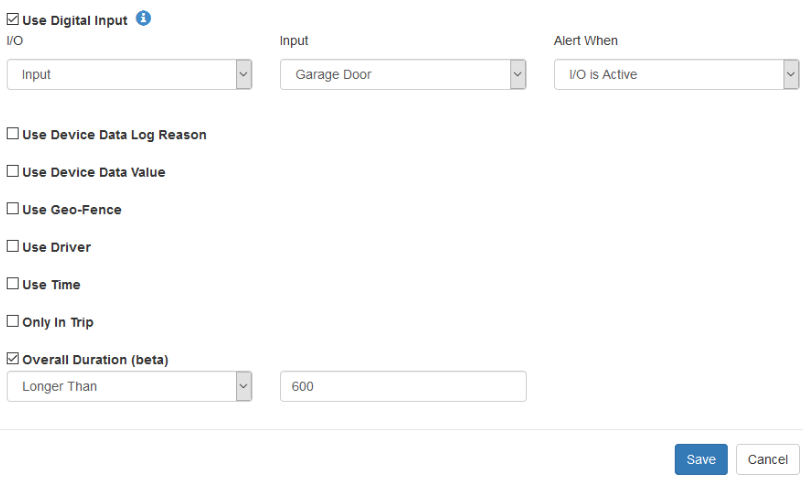
Alternatively, the Panic/Duress Button Alert from the Alert Wizard can be used - just use the Digital Input you are using with the reed switch, and a more accurate name at the end of the set up.
Reporting on Door Being Left Open
It may not be of much interest if the door is simply opened or closed, but important if it remains open. The "Duration" condition of the Alert setup can be used
The above issue shows set up for an alert to fire if the door remains open for over 10 minutes.
However for this scenario it is important that "Upload on Inactive" is selected in OEM so we know immediately when the door is closed again.
There are also some caveats to this set-up which are discussed here Duration Condition for Alerts
Reporting on Door Open/Close
To run a report on the times and duration the door was opened, we can set up a Custom Event. An Alert is the email/SMS sent due to a condition occurring, and an Event can be thought of the way this is recorded for later reporting, via the Event Reports.
To set up an event, go to Admin -> Event Types
We want to log on the Start and End of Event, so the time that the duration the door was left open for can be monitored. In this scenario the other logging is not relevant - e.g. Distance, Geofence etc. However if it was door on a truck etc that moves, Distance may be relevant, it depends on the application.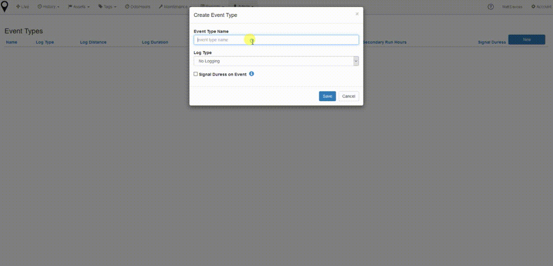
Now we can return to the Asset's I/O mappings and link Digital Input 1 to the Event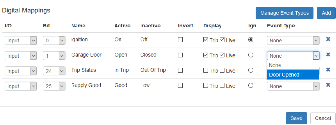
A record of door opens/closes will be available in the Custom Events - Summary, and Custom Events - Detail Reports
Battery Powered Devices
Applies To
| Device | Firmware Version |
| Yabby GPS/ Yabby V3 | All FW Versions |
| Yabby Edge / Oyster Edge | All FW Versions |
| Oyster2/Oyster3 | All FW Versions |
| Remora2/Remora3 | All FW Versions |
| Barra GPS | All FW Versions |
| Barra Core / Barra Edge | All FW Versions |
| Manta Fusion | All FW Versions |
| Manta GPS | All FW Versions |
Battery powered devices can be used to detect door open/closed particularly for applications where no external power is available.
There are 2 ways we can configure the parameters in order to send updates on accelerometer movement.
- Configure High-G Event Detection. If we exceed the G-Force threshold there is movement of the door.
- Configure the device to Jostle Mode Tracking - where a trip start = movement of the door.
Neither method is 100% reliable, and neither can tell us the ‘state’ (open/closed) of the door - just that accelerometer activity occurred.
This may be enough for simple solutions such as detecting unauthorised access - where a door, room, shipping container etc should not be/is rarely opened and any accelerometer activity will alert us to theft.
Jostle Mode
Our battery powered devices feature Jostle Mode Tracking where accelerometer activity is used to detect trips/movement, i.e, when accelerometer activity is detected, a trip is started and we can set the device to upload for an alert. Then once it has sat still for a while (timeout configurable) - the trip will end.
Please refer to Default Tracking Parameters for more details on different tracking modes.
So for this application, a Trip Start = Door Open (Movement)
This setup is not 100% foolproof. Below are some key points that need to be considered
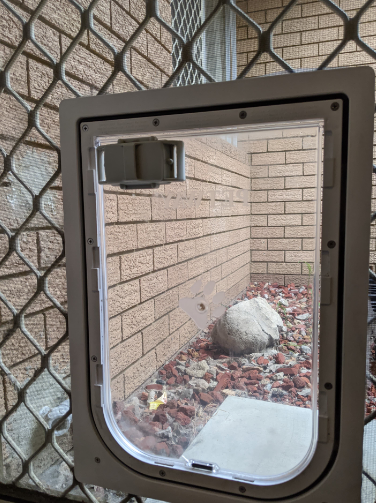
- Install is super simple, see image below
- We need to be careful with how we choose our accelerometer wakeup parameters (i.e. how much movement causes a trip start) - to avoid missing a door open/close event, or generating false ones
- The device is only looking at accelerometer activity, so for example if a sea container is loaded onto a truck - it looks the same as door open/closed.
- We can't distinguish definitively between open/closed - just movement of the door
- We can't detect multiple events <60s -60 sec is the minimum trip end timeout configurable.
 |
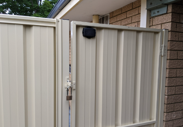 |
This may sound like instructions to avoid this setup! But it is not the case, just things to be aware of. For example sea containers are an excellent example of a what this would work for. Perhaps they sit in the yard for long periods, and we just need an alert if anyone opens the door. The container would sit very still, so as not to prevent false alerts - and we'd get an alert if there was unauthorized entry, and can action it. We wouldn't be able to say the door was opened and closed exactly 50 times - but perhaps this isn't necessary information.
Installation Overview
First we have to look at how to attach the device and the positioning factors that come into play. If you're trying to monitor movement on an interior door that doesn't have a good view of the sky for GPS positioning, the Yabby Edge or Oyster Edge will be a good option to go with.
There are two main levels when using the accelerometer to detect door/gate movement. You can disable the wake filter to make even the slightest bump will wake the device up, or you can configure the wake filter to measure a certain type of movement.
For the first option - for any tiny movement to make the device upload, we want to have upload on movement detection and Disable Wake filter set to Yes.

We have set the trip end time to 60 sec in this case. If you're installing a device on a doorway that is used for x minutes at a time, you could set the end trip to slightly longer than this to reduce multiple alerts.
We can disable logging* and uploading during trip off since we are only interested if the door has moved at all, rather than monitoring usage after the door is opened.
Edge Devices:

Traditional Devices:

*in-trip logging can be set down to 10s for traditional devices in the basic tracking tab
We can also adjust the adjust the accelerometer settings to configure what level or movements will start a trip. The wake-up threshold is the force of the movement and the wake-up count is how long it persists for.

These settings come into play with what your use case is, if you have a gate that gets bumped by the wind on it's latch normally, but you want to know when it's opened you can set the wake-up count to be higher to filter out the short jostles.
By the same token you can set the wake-up threshold higher so you only want to the asset to upload when a strong bump is identified for either a long or short period as determined by the count.
After Hours Detection
If you wanted to have high resolution reporting after hours, you can set up a second set of movement detection parameters which the device will use once it moves into the declared time period. The settings in this tab are the same as the standard movement detection. Adaptions you could make are:
- No logging or uploads on movement detection during 9am - 5pm, but uploads on movement detection between 5pm and 9am
- Enable wake filter during 9am - 5pm to only detect larger movements and disable to detect slight jostles after hours.
Parameter setup for After Hours Movement can be found here: After Hours Movement
Using Bluetooth Tags
Applies To
| Device | Firmware Version |
| G120 | All FW Versions |
| Oyster3 4G Ble | All FW Versions |
| Oyster Edge 4G | All FW Versions |
| Remora3 4G | All FW Versions |
Our Bluetooth Gateway devices can pickup a BLE magnetic Sensor Tag to detect door open. See list of all currently integrated tags here 3rd Party Bluetooth® Tag Support.
For the ELA Mag Tag, an alert can be set based on whether the tag and the magnet have been separated, signifying a door open/close event. Please see Bluetooth® Tag Alerts on Telematics Guru for more information.
The G120 has an option for continuous BLE scanning and option to upload when a tag update is logged. The scanning period on the Oyster Edge, Remora3 and Oyster3 can be brought down to replicate the continuous scanning on the G120, however this comes at the cost of high battery usage.
