Getting Started - SensorNode Bluetooth®

Written by Matthew Clark-Massera
Updated at October 29th, 2025
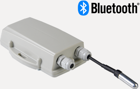
This guide covers set up the SensorNode Bluetooth® and reading the data via a DM Gateway device (Eagle, Remora2, G120, G150).
The device has multiple inputs, all of which it will sample and transmit the values/status via Bluetooth. The available inputs are:
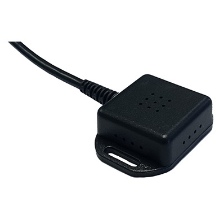
- An I2C Interface for use with up to 2 x DM Temp Probes and 1 x Temperature/Humidity Sensor simultaneously
- 2 x 0-30V Analogue Input
- 2 x Digital Inputs.
Note, for Telematics Guru users, a maximum of 2 x SensorNodes can be used per gateway device, and only Temp/Hum and Temp Probe readings can be displayed in TG.
digitalmatter.com
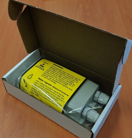
In the Box
In the SensorNode box you'll receive a DM SensorNode, with 6 two glands (in place). The PCB is screwed into the housing with four screws, with six screws for securing the housing lid and an pre-installed seal for ensuring an IP67 seal.
One gland will be fitted with a stopper to prevent water ingress when no cable is fitted. DM can supply extra stoppers if both are going to be unused, or as replacements.
Setting it Up
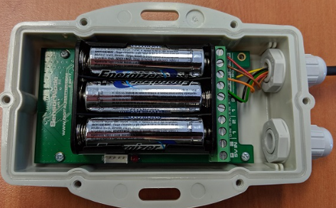
Batteries
The SensorNode uses three off the shelf AA Lithium Batteries and does not have reverse voltage protection so take care to insert the batteries with the correct polarity, the tabs being the negative terminals.
Alkaline batteries may be used, but LiFeS2 batteries will give superior performance.
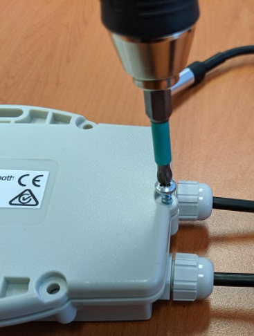
Housing
Once any wiring is done (see below) and batteries are installed, all that remains is to seal the housing. Seal the device carefully to achieve the IP-67 rating. Ensure that the clear silicon seal is in good condition, is lying flat, and is not fouled by any plastic debris or other material.
- Close the housing, and gently squeeze it shut. Foam on the lid will compress against the batteries, holding them firmly in place.
- Tighten the 6 screws to a uniform tightness. On the first assembly, the screws may be quite stiff.
- If you wish to replace the batteries and open the housing, be sure to check that the silicon seal is in good condition before closing the housing again.
What does the SensorNode BLE Broadcast?
By default, the SensorNode will sample all inputs every 30 seconds, and update their values. It then sends a BLE beacon containing all values every 2 seconds. The BLE frame contains:
- Tag Serial number
- Tx Power
- Battery Voltage
- Internal Temperature (from microcontroller, not highly accurate)
- DM Temp Probe Readings
- DM Temp/Humidity sensor reading
- Digital Input states
- Analogue input states
If any of the above sensors aren't connected, the field will just be 0. Those using 3rd party platforms will see the tag data in fields 29 and 30.
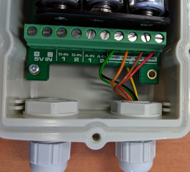
Wiring in Sensors
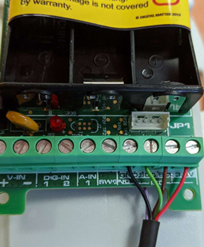
Please note, Wires will need to be inserted through the gland in the housing first, then wired into the PCB.
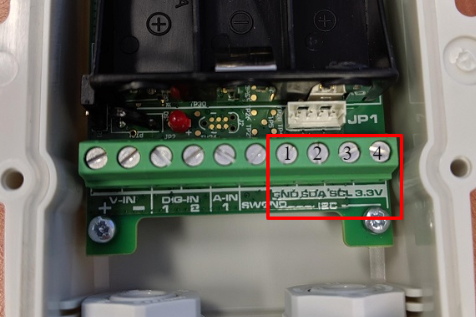
On the board, you will see a strip of screw terminals, 4 of them are used for the I2C Bus.
- GND
- SDA
- SCL
- 3.3V
The connections for each sensor are as follows:
DM Temperature Humidity (Ambient) Sensor
Wiring Table
| Wire Colour | Function | PIN on PCB |
|---|---|---|
| Red | Positive | 3.3V |
| Brown | Clock | SCL |
| Green | Data | SDA |
| Black | Ground | GND |
| Purple | - | Not used |
DM Temperature Probe 1 or 2
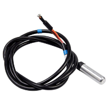
Each I2C sensor has an address. For the Ambient sensor this is set at the factory and fixed to one address.
The Temperature sensor can be given 1 of 2 addresses, depending on how it is wired (green wire sets address).
Connections are as follows:
| Wire Colour | Function | Inserts into |
|---|---|---|
| Red | Positive wire | 3.3V |
| Brown | Clock | SCL |
| Orange | Data | SDA |
| Black | Ground | GND |
| Green | Address Selection | Ground for Temp Sensor 1 3.3V for Temp Sensor 2 |
Note
Where the green wire is connected dictates which sensor you should select when setting up your system parameters. E.g it is connected to GND, set the Falcon up to measure "DM Temp Probe 1"
The wiring for the connection of a Digital Matter Temperature Probe 1 is shown below
Viewing Sensor data in 3rd Party Platforms and Telematics Guru
See Connecting a SensorNode Bluetooth® to a Remora2, G120, G150 for instructions