Generic Modbus RS485 Action
A guide on setting up Modbus Actions on the Hawk
Table of Contents
Please Note
For these actions to work you will need:
- Hawk Pro (FW 1.6 or later) OR Hawk Lite (FW 1.1) or later
- RS-1 Card on FW 1.5 or later
Modbus Actions are designed to be highly flexible and configurable, to enable you to integrate Modbus RS485 Sensors with the Hawk.
In order to do this, it is important to have as much information about your sensor and use case as possible.
For example, you'll need your Modbus protocol specification, and you'll need to understand what information you want to actually get from the device.
For an example of this configuration with a specific sensor - please see this article.
This action comprises multiple settings. Most of them can likely remain on defaults for simple integrations.
The settings below are identical for all Modbus Actions.
Configuring additional Modbus Actions
Please note that when connecting 2 different sensors, and configuring additional Modbus Actions to work with Modbus Action 1 there are a few considerations to be had.
- Both Actions share the common settings of the RS1 card tab.
- The sensors need to have the same Modbus baud rate and Modbus parity.
- They must have different sensor addresses (if you are sampling 2 different sensors)
- If sampling 8+ registers from the same sensor, the subsequent actions will have the same address.
- They must save to different analogues on the Hawk.
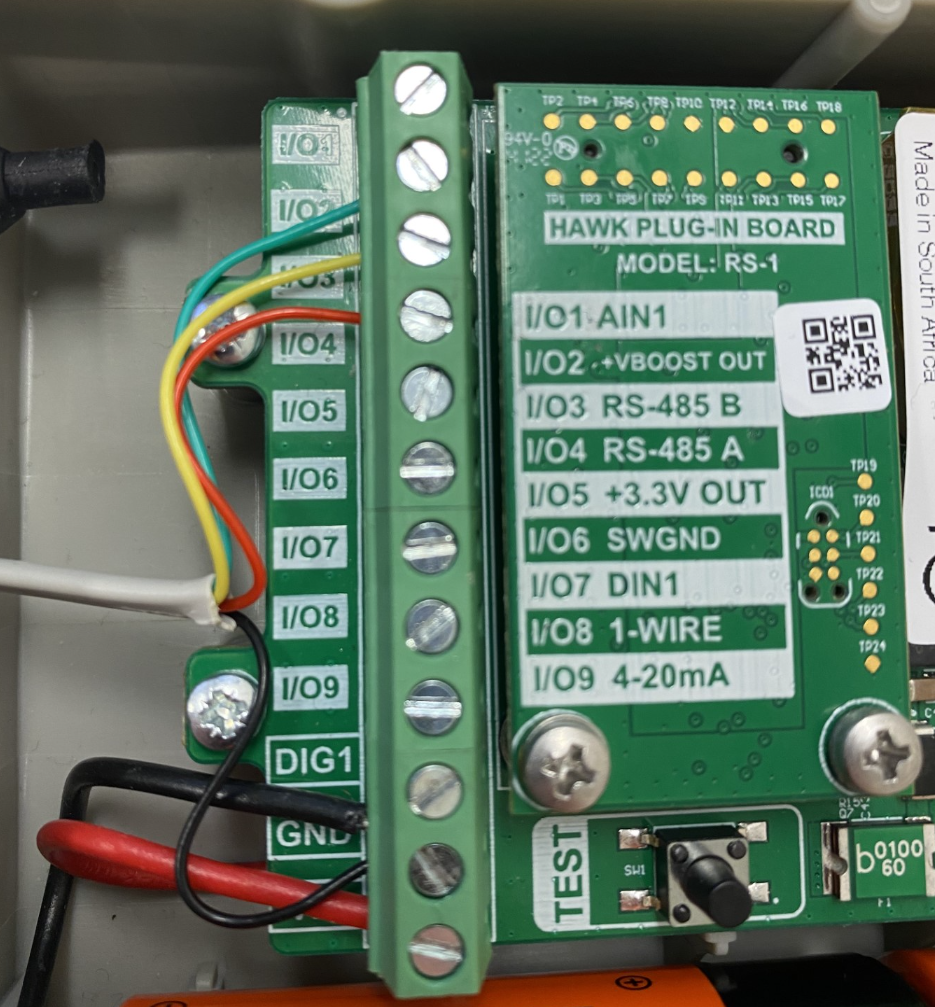
Sensor Wiring
Example Wiring
Please note:
The below wiring guide is just an example. Exact wire colours will be sensor-dependent.
In addition, the VCC wiring is sensor-specific. Sensors with a 3V3 voltage requirement should be wired to the 3V3 out. Sensors with 5V or 12V requirements should be wired to the Vboost, which should be configured appropriately in the RS1 Tab.
Wires |
Hawk I/O |
Description |
Green |
I/O 2 |
VCC |
Black |
GND |
GND |
Red |
I/O 4 |
485_A |
Yellow |
I/O 3 |
485_B |

RS1 Card Tab
There are a few settings you will need to change on the RS-1 tab, depending on your wiring configuration.

Modbus Reading Sets 3.3V
Does the Modbus action turn on the 3.3V output? If powering the RS485 sensor with the 3.3V rail, then it should be set to “Yes”.
Modbus Reading Sets SWGND
Does the Modbus action set the Switch Ground?
Modbus Reading Sets Vboost?
Does the Modbus action turn on the Vboost output? If powering the RS485 sensor with the 5V or 12V, then it should be set to “Yes”.
If you are powering a sensor with Vboost, you will also need to specify the voltage level as 5V or 12V in the RS-1 Card tab(See below).

Modbus Action 1 Tab

General Settings
Sensor Address
What sensor address should be used? This should be in the sensor datasheet or in its Modbus protocol documentation.
If you cannot find the sensor address, try “1”. If that doesn't work, contact the sensor manufacturer for support.
Power On Delay
This corresponds to the sensor warmup time (in seconds). This is only applicable to some sensors. If it's needed, it will likely be mentioned in the sensor datasheet.
This time is the amount of time before sampling that the sensor will be powered from the Hawk card.
Analog Offset
The Analog in which to save the first sensor reading (Reading 1 or R1).
Subsequent readings will be saved in analog offset +1 etc.
Configuring Readings 1 to Reading 8.
Now to the “Reading” sections. Each reading (R1 to R8) is configured identically. You only need to configure the readings needed for your specific sensor.
Reading 1. Function
The options here are:
- None
- Read Holding Registers (03 or 0x03)
- Read Input Registers (04 or 0x04)

“None” is only selected if you don't need to enable this reading.
Selecting a Holding Register vs an Input Register depends on your specific sensor query. This information should be in your sensors Modbus Protocol document.
Holding
R1. Register Address
The specific address of the register you are trying to query.
R1. Datatype
The datatype of the register.

We can cater for multiple different data types (see above).
R1. Byte Order

Select the byte order of the of the register.
Assume big-endian if unspecified in the Modbus communication protocol.
R1. Scaling 10 Exponent (x)
This scaling factor multiplies the reading by 10^x. X can be negative.
The reason for this is that we save the value of the register to an Analog, which is in an INT32 format. Only integers/whole numbers can be saved to these analogs.
If the value of the register is a float (e.g. 24.57), you will need to multiply by 100 (x =2) to remove the decimal point and save 2457 to the register.
Your sensor datasheet or Modbus spec may give you some idea of the data output format. Else, your best bet is to test it out and see.
Adding a Second Modbus Sensor
It is also possible to connect two RS485 Modbus RTU sensors in parallel via the RS485 I/Os. These can be configured via separate Modbus actions in the System Parameters for the Hawk:

However, when attempting to connect two RS485 Modbus sensors, the following must be noted:
- The sensors must have the same baud rate as configured in the RS-1 parameters tab
- The sensors must have the same parity, as configured in the RS-1 parameters tab
- The sensors must have different addresses
