Connecting a DM iButton Reader
Learn how to connect a iButton reader to an Arrow Global BLE, Dart3, G120, G70

Written by Matthew Clark-Massera
Updated at August 7th, 2025
Table of Contents
| Supported Devices |
| Arrow Global BLE |
| Dart3-2G and Dart3-4G |
| G120-2G and G120-4G |
| G150-Global |
| G70-2G and G70-4G |
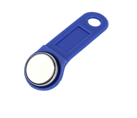
Digital Matter can supply an iButton reader and tags for use with the above devices.
 |
 |
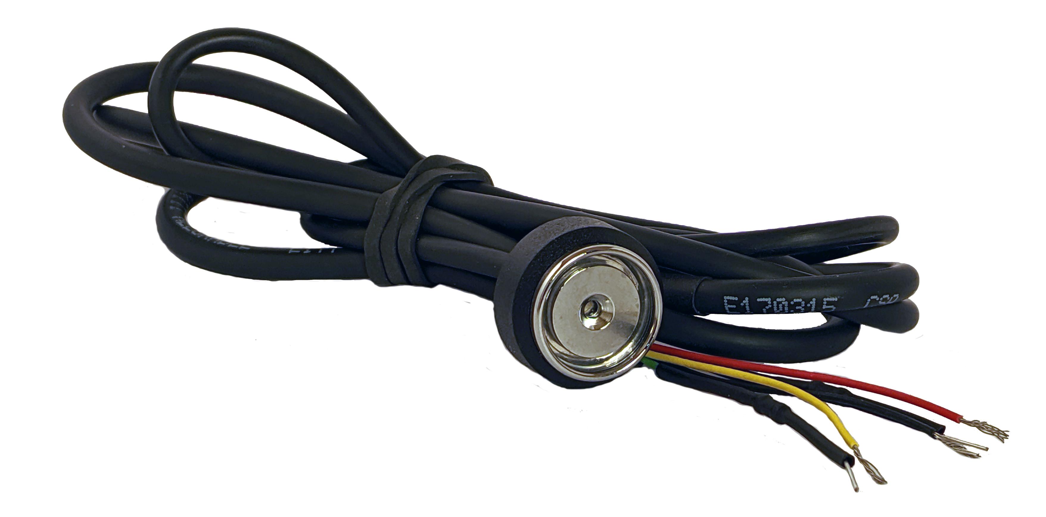
The Digital Matter iButton Reader has the following wire colours:
| Wire Color | Function |
|---|---|
| Red | iButton Signal Line |
| Black | Ground |
| Green | Green LED (with 1000 ohm resistor) |
| Brown | Red LED (with 1000 ohm resistor) |
| Yellow | LED Negative |
Connecting an iButton Reader to the Arrow Global BLE Harness
See the Arrow Global BLE Wiring and Installation guide for full connectivity guidance.
Connecting iButton to the Arrow Global BLE is a simple two wire connection.
- Connect Brown (1-Wire #7) to the Red iButton Signal Line
- Connect a Black wire (Arrow GND wire #8) to the Black iButton Ground line

System Parameters
The Arrow Global BLE must be told to expect an iButton input in parameters, this can be achieved by updating the system parameters to include the 2 Wire Function and Driver ID tabs. For basic Driver ID with no immobilisation, the settings are outline below:


Once the connections are made and the system parameters updated and loaded, the Arrow Global BLE will be able to read the iButton data.
Note: Some iButton readers require the Poll iButton parameter to be enabled.
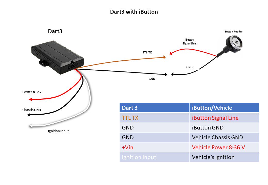
Connecting an iButton Reader to the Dart3 Harness
Dart 3 Wiring Guide - DART3 12-wire Harness Definition.
Cut the 4 way Molex plug off the Harness. (Ensure you won't be using it with a DM RFID reader first)
- Connect Brown (Driver ID 1 - Pin 10) to the Red iButton Signal Line
- Connect a Black wire (Dart3 Ground) to the Black Ground on the iButton reader
Parameters
The Dart3 must be told to expect an iButton input in parameters, by default it is expecting DM RFID reader input over these wires.

Advanced: LED Flash Output
The System Rail Output wire (Purple) can be used to control the in-built LED - i.e. to turn on/off when a tag is read to indicate ‘success’.
If you wish to use the LED in the iButton harness, connect the following:
| Dart Harness | IButton Wire |
|---|---|
| Purple (System Rail out) |
LED Positive Wire
|
| Black (Ground) | LED Negative (Yellow) |
Special System parameters required:


LED turns on with Ignition
| iButton Wire | Dart Harness |
|---|---|
| Brown Or Green (If you want the LED to change colour on ignition, connect one LED to External Power) |
White-Ignition |
| Yellow | Black |
| Black | Black |
| Red | Brown |
LED Turns off with Tag Scan
This can be used in conjunction with an immobiliser, for detailed instructions see the following articles:
- Immobiliser Install - Asset starts after valid Driver ID Scan
- Immobilisation Install - Asset can be immobilised from server
| iButton Wire | Dart Harness Wire | Relay Wire |
| Red | Brown & Green | - |
| Brown and/or Green | Red | Purple |
| Yellow & Black | Yellow | White |
Special System parameters required:

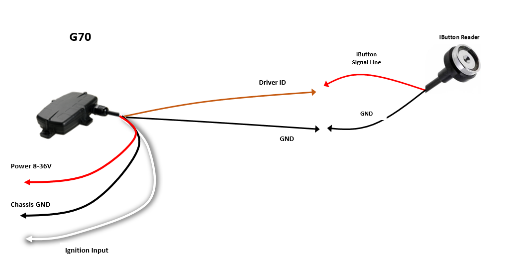
Connecting an iButton Reader to the G70
G70 Wiring Guide - G70 Harness Definition
- Connect Brown (Driver ID 1/iButton Line) on the G70 to the Red iButton Signal Line
- Connect the Black iButton wire to Ground
Parameters
The G70 must be told to expect an iButton input in parameters, which it is by default under the Driver ID Function tab.
Connecting an iButton Reader to the G120
- Connect Brown and Green (Pin 13 and Pin 14) on the G120 to the Red iButton Signal Line on the iButton reader
- Connect the Black iButton wire to Ground
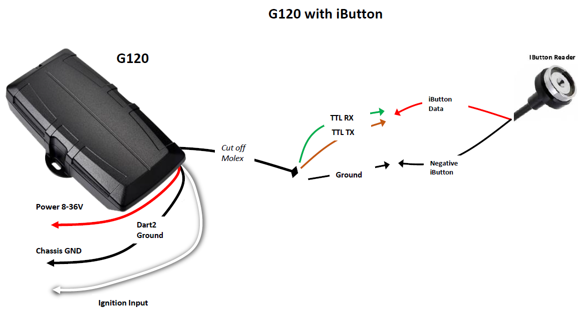
Parameters
The G120 must be told to expect an iButton input in parameters. This is done from the 4 Wire Plug Function tab.

Once the connections are completed, the device can read the iButton data.
Connecting an iButton Reader to the G150
Firmware Requirement
Requires FW v1.7+
- On the G150, connect the Brown and Purple (Pin 6 and Pin 7 of Harness 1) to the Red iButton Signal Line on the iButton reader
- Connect the Black iButton wire to Ground
Parameters
The device must be told to expect an iButton input in parameters. This is done from the 4 Wire Plug Function tab.

Once the connections are completed, the device can read the iButton data.